What Makes a Reliable Electrical Harness
A reliable electrical harness uses 22–24 AWG copper wires with PVC insulation (90°C rating), features crimps tested to ≥50N pull force, meets IPC/WHMA-A-620 for terminal retention, and withstands -40°C to +125°C operational ranges.
Materials and Insulation
Over 70% of harness failures can be traced back to the degradation of insulation or the conductor itself. Selecting the right materials isn't just about functionality; it's a critical economic decision. Using a higher-grade, 105°C rated PVC insulation over a standard 80°C type might increase the initial wire cost by approximately 15-20%, but it can extend the harness's service life by over 10 years in an engine bay environment, preventing costly recalls and warranty claims.
A 20-gauge OFC strand can handle a continuous current of up to 5 amps with minimal voltage drop, whereas an aluminum equivalent might require a thicker 18-gauge wire to achieve the same performance, compromising bundle size and flexibility. Most automotive wires use a stranded design with 19, 26, or 41 individual strands for a given American Wire Gauge (AWG) size. A higher strand count, like 41, offers better resistance to metal fatigue from vibration, a primary cause of breakage.
Insulation is the first line of defense. The material must be chosen based on the operating environment. Common options include:
- PVC (Polyvinyl Chloride): A general-purpose, cost-effective option rated for temperatures typically up to 80°C or 105°C. It is flexible and durable but can become brittle at low temperatures (-40°C) and is susceptible to damage from oils, fuels, and solvents.
- XLPE (Cross-linked Polyethylene): Offers excellent thermal resistance, with a common rating of 125°C. It has better resistance to chemicals and abrasion than PVC. The cross-linking process creates a polymer structure that does not melt easily, making it suitable for high-temperature environments near engines.
- PTFE (Polytetrafluoroethylene): Used in extreme environments. It is highly inert, resistant to almost all chemicals, and can operate continuously at temperatures up to 260°C. Its primary drawback is significantly higher cost, often 5-10 times that of standard PVC wire.
| Material Property | PVC (105°C Grade) | XLPE | PTFE |
|---|---|---|---|
| Max Temp Rating | 105°C | 125°C | 260°C |
| Flexibility | Excellent | Good | Fair |
| Abrasion Resistance | Good | Very Good | Excellent |
| Chemical Resistance | Fair | Good | Excellent |
| Relative Cost | $ | $$ | $$$$ |
A thin wall of 0.25 mm might be sufficient for a low-voltage data cable in a protected location, but a power cable in a harsh environment might require a 0.6 mm wall for improved dielectric strength and abrasion resistance. For a 16 AWG wire, a 0.5 mm wall of XLPE insulation can typically withstand a 600V test voltage, providing a safe margin for a 12V or 48V automotive system.
Secure Connections and Terminals
Industry studies indicate that approximately 40% of all electrical harness malfunctions originate at termination points. These failures are rarely sudden; they often begin as a high-resistance connection that generates heat, leading to voltage drops, data errors, and ultimately, thermal runaway. In automotive applications, a single corroded terminal can increase resistance from a standard 2-3 milliohms to over 50 milliohms, causing a localized temperature spike of more than 150°C.
For a 20-gauge wire, a typical crimp height might be 1.1 mm ± 0.05 mm. An under-crimped connection (e.g., 1.3 mm) will be loose, leading to high resistance and eventual failure from vibration. An over-crimped connection (e.g., 0.9 mm) will cut some of the copper strands, reducing the current-carrying capacity and creating a point of mechanical failure. Using an calibrated, automatic crimping tool improves consistency and reduces error rates by over 90% compared to manual hand tools.
A 0.5-micron gold flash on a terminal contact can reduce surface contact resistance to less than 5 milliohms and maintain that performance for over 10,000 mating cycles. The connector housing must provide both physical latch security and environmental sealing. A primary seal on the wire itself (often a rubber grommet) prevents moisture wicking along the strands, while a secondary seal on the connector housing interface blocks bulk water ingress. Connectors are rated by an IP (Ingress Protection) code; a rating of IP67 guarantees protection against dust and immersion in 1 meter of water for 30 minutes.
Always perform a pull-force test to validate a crimped terminal. For a standard 0.5 mm² (20 AWG) wire, a well-executed crimp should withstand a steady pull force of at least 50 Newtons (approximately 11.2 lbf) for 10 seconds without any signs of detachment or wire slippage. This quantitative test is a direct measure of mechanical integrity.
They should be designed so that the bend radius of the wire is never less than 1.5 times the wire's outer diameter. In high-vibration environments like engine mounts, using a braided sleeve or conduit to bundle and secure a group of wires can reduce the peak stress on individual connections by over 60%, dramatically extending the harness's operational life beyond the typical 15-year service target.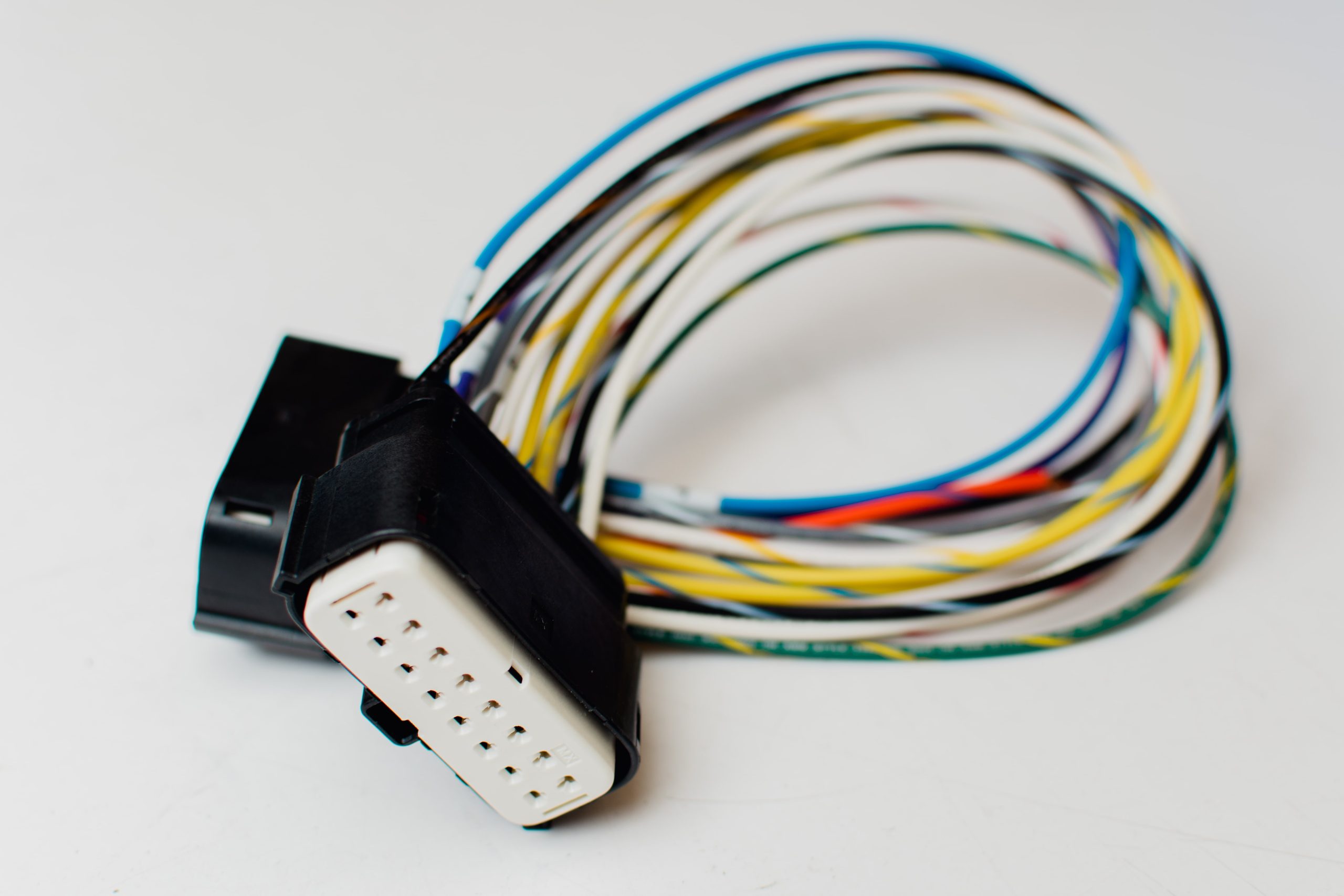
Testing and Quality Checks
Statistics show that a comprehensive testing protocol can catch over 95% of potential failures before the harness leaves the factory, reducing field failure rates to less than 0.1%. The cost of identifying a fault during manufacturing is typically 10-100 times less than the cost of a warranty repair in the field, which often involves disassembling entire vehicle sections. For a mid-volume automotive program, this can translate to saving over $500,000 annually in avoided warranty and recall expenses.
A computerized continuity test checks for opens, shorts, and miswires by verifying resistance paths between every designated point in the connector(s). This test applies a low current (typically 100-200 mA) and measures resistance; a reading above 5 ohms might flag an open circuit, while a reading near 0 ohms between two unrelated pins indicates a short. Following continuity, a hi-pot test stresses the insulation integrity. For a 12V automotive system, a test voltage of 500V DC applied for 2 seconds between all conductors and the shield is standard. The leakage current must remain below a strict threshold, often 5 µA, to pass.
| Test Type | Standard Parameters | Pass/Fail Criteria |
|---|---|---|
| Vibration Test | 10-2000 Hz frequency sweep, 15 m/s² acceleration, 100 hours per axis | No broken strands, resistance change < 5% |
| Thermal Cycling | -40°C to 125°C, 1000 cycles, 1-hour dwell times | Insulation must not crack, conductor resistance stable |
| Salt Spray (Corrosion) | 5% NaCl solution, 35°C, 500-hour exposure | Terminal contacts must show minimal corrosion, contact resistance change < 10% |
| Seal Integrity (IP67) | Immersed in 1 meter of water for 30 minutes | No water ingress inside connector cavities |
A simple gauge check, which inserts a 0.5 mm thick feeler gauge between the terminal and the housing, should not fit if the terminal is properly seated. Furthermore, the tensile strength of crimps is destructively tested on a sample basis using a pull force tester.For a 2.0 mm² wire, the crimp must withstand a pull force of at least 150 Newtons without the wire extracting from the terminal. This quantitative data is recorded for statistical process control (SPC) to monitor production tooling wear and prevent drift into out-of-spec conditions. Implementing a thorough traceability system, often via barcodes on each harness, links every component back to its production batch, machine, and operator, enabling rapid root-cause analysis if a defect is ever discovered.
Protection from Environmental Damage
Studies indicate that environmental factors contribute to over 30% of all harness-related warranty issues. For example, a single drop of saltwater mist can create a current leakage path of over 50 µA between adjacent pins, leading to intermittent faults that are incredibly difficult to diagnose. Proactively shielding the harness from these elements isn't an extra cost; it's a critical investment.
Braided polyester sleeving with a thickness of 0.75 mm can increase the abrasion resistance of a wire bundle by a factor of 10x compared to an unprotected wire, surviving over 50,000 repetitive rub cycles against a sharp metal edge. For extreme heat areas near exhaust manifolds, where temperatures can exceed 600°C, fiberglass or silicone rubber sleeves are mandatory. A 1.5 mm thick silicone sleeve can reduce the radiant heat exposure to the wires inside by over 200°C, maintaining the conductor temperature within its 150°C rating. In areas with high risk of impact, such as under the vehicle, corrugated nylon conduit with a wall thickness of 1.2 mm provides a crush resistance of over 500 Newtons, protecting the wires from road debris and pinching during assembly.
When heated to 120°C for 60 seconds, a dual-wall polyolefin tube with a 1.0 mm wall thickness will shrink to half its diameter and extrude a sealant that creates a 100% waterproof bond, with a pull strength exceeding 80 Newtons. For areas exposed to gasoline, oil, or brake fluid, chemical-resistant materials like fluoropolymer (FEP) heat-shrink are required, as standard materials will degrade and swell within weeks.
| Protection Type | Material Example | Key Specification | Primary Application |
|---|---|---|---|
| Abrasion Sleeve | Braided Polyester | 0.75 mm thickness, 50,000 rub cycles | Routing through body panels, sharp edges |
| Heat/Flame Sleeve | Fiberglass | 1.5 mm thickness, 600°C continuous | Near exhaust, engine block |
| Waterproof Seal | Adhesive Lined Heat-Shrink | 3:1 shrink ratio, 80N peel strength | Splices, branch points, end seals |
| Chemical Resistance | FEP Heat-Shrink | Resists ASTM #3 Oil @ 125°C for 1000h | Fuel pump, transmission, brake lines |
| Crush Protection | Corrugated Nylon | 1.2 mm wall, 500N crush load | Underbody, chassis passages |
Securing the harness with clamps every 150 mm prevents excessive movement that leads to fatigue and abrasion. Maintaining a minimum bend radius of 10 times the harness diameter is critical; forcing a 20 mm thick bundle around a 100 mm radius bend stresses conductors and can immediately reduce the insulation's lifespan by 70%. Always route the harness away from direct heat sources and sharp edges, using existing brackets and clips. This careful planning during installation costs nothing in parts but drastically reduces the environmental stress the harness will face over its 15-year design life.
Good Design and Layout
Up to 50% of assembly time can be wasted wrestling with a poorly laid-out harness that doesn't fit as intended. A design that reduces the number of assembly steps by just 10% can save an automaker over $1 million annually in labor costs on a high-volume production line. Good layout begins with a clear understanding of the vehicle's architecture, ensuring the harness is the right size, uses the correct wires, and follows an efficient path that minimizes stress and maximizes serviceability. Key principles include:
- Minimizing total length to reduce voltage drop, weight, and cost.
- Grouping wires by destination and function to simplify assembly and troubleshooting.
- Planning for service loops and accessibility to allow for repairs without full harness replacement.
- Accounting for thermal management by separating high-current and sensitive signal wires.
Correct wire gauge selection is a non-negotiable calculation, not a guess. For a 10-amp load over a 5-meter run in a 12V system, using an 18 AWG wire would result in a 6% voltage drop (0.72V), which is unacceptable for most sensors. Upsizing to 16 AWG reduces the drop to 3.7% (0.44V), while 14 AWG brings it down to a robust 2.3% (0.28V). This calculation must be performed for every circuit to ensure all components receive stable voltage. Furthermore, grouping wires by their function and noise immunity is crucial. High-current AC wires (e.g., for a compressor) should be routed at least 100 mm away from low-voltage sensor lines (e.g., CAN bus) to prevent inductive noise coupling that can cause data errors. Twisting signal pairs at a rate of 40 twists per meter provides inherent noise immunity, reducing electromagnetic interference (EMI) by up to 20 dB compared to parallel runs.
A primary goal is to keep the bundle diameter under 14 mm for flexibility; larger bundles are stiff and difficult to route through tight spaces. This often requires splitting one large bundle into two or three smaller, more manageable sub-harnesses. The bend radius must be carefully controlled; the absolute minimum for a typical harness is 10 times its outer diameter. Forcing a 10 mm thick bundle around a 50 mm radius bend will immediately stress every component and can reduce the wire's flex life by over 70%. Use the following table as a guide for key physical design parameters:
| Design Parameter | Typical Value or Calculation | Impact of Deviation |
|---|---|---|
| Wire Gauge Selection | Based on 3% max voltage drop calculation | Voltage drop >5% can cause sensor malfunctions |
| Bundle Diameter | Target < 14 mm for flexibility | Bundles > 20 mm become rigid and hard to install |
| Minimum Bend Radius | 10 x Harness Diameter | Smaller radii cause insulation stress & conductor fatigue |
| Wire Separation | 100 mm between high & low power | Inductive coupling causes signal noise and errors |
| Clamp Spacing | Every 150-200 mm along the run | Excessive movement leads to abrasion and fatigue |
Using one type of 4-pin connector on 80% of sensors, instead of 10 different custom ones, reduces assembly errors by 25% and cuts inventory costs. Clearly labeling every wire within 50 mm of its connector with a permanent, laser-etched marker that includes the circuit number (e.g., ECU_12V_IGN_05 ) allows a technician to diagnose a fault in minutes, not hours. Including a 100 mm service loop at major connection points, like behind the instrument cluster, allows for connector re-termination without needing to replace the entire harness, saving hundreds of dollars in repair costs and vehicle downtime.
Handling and Installation Tips
It's estimated that roughly 25% of harness failures in the first year of service are directly attributable to damage during the assembly process. A single kink in a wire from improper pulling can reduce its flex life by 90%, and overtightening a zip-tie by just 2 Newton-meters can compress insulation enough to cause a short circuit months later. These mistakes are costly; repairing a damaged in-vehicle harness often requires 3-4 hours of labor at a rate of $120/hour, making prevention the only cost-effective strategy. Proper handling isn't about brute force; it's about technique, awareness, and using the right tools for the job. Key principles include:
- Preventing abrasion during routing by protecting harness edges.
- Pulling by the connector, never by the wires, to avoid terminal damage.
- Maintaining minimum bend radii to avoid internal conductor damage.
- Using torque-controlled tools for fasteners to prevent crushing.
Always inspect it on a clean, flat surface—like a 6-foot long felt-covered table—before installation. Unroll it gently; never drag it directly across the floor, as concrete can act like sandpaper on the insulation. When pulling the harness into place, never exert more than 50 Newtons (approx. 11 lbf) of pull force on the bundle itself. Exceeding this can stretch wires, displace seals, and pull terminals partway out of their connectors. Always pull from a robust point, ideally a strong connector housing. For routing through sheet metal holes, always use a grommet or a protective sleeve. The force required to pull a 20 mm diameter harness through a bare metal hole can be 40 Newtons, but with a plastic grommet installed, this drops to under 15 Newtons, drastically reducing the risk of damage.
Mating a connector should require a firm but manageable force; if it feels excessively stiff (over 60 Newtons of insertion force for a 20-pin connector), stop and inspect for bent pins or misaligned terminals. Forcing it can cause thousands of dollars in ECU damage. Once connected, always engage the secondary locking mechanism—the audible click is non-negotiable. When securing the harness with clamps or zip-ties, use a calibrated tool. A zip-tie tensioned to 20 Newtons provides secure bundling, but if overtightened to 50 Newtons, it can compress the insulation by up to 30%, potentially damaging the wires inside.
| Installation Step | Key Parameter / Tool | Risk of Improper Technique |
|---|---|---|
| Harness Pulling | Max Force: 50 N (11 lbf) | Stretched wires, displaced seals, pulled terminals |
| Connector Mating | Max Force: 60 N for 20-pin | Bent pins, damaged ECU, intermittent connections |
| Zip-Tie Tightening | Torque: 2.5 Nm or Tension: 20 N | Insulation compression, wire damage, hidden shorts |
| Bend Radius | Minimum: 10 x Bundle Diameter | Conductor fatigue, insulation cracking, reduced life |
| Ground Connection | Torque Wrench: 8-10 Nm for M6 bolt | High resistance, voltage drops, overheating |
Clean the grounding point to bare metal using a wire brush or abrasive pad until it shines, ensuring a contact area of at least 25 mm². Apply a thin layer of antioxidant compound (e.g., zinc-loaded grease) to prevent future corrosion. Secure the ground ring terminal with a star washer and torque the M6 bolt to the specified 8-10 Nm. An under-torqued bolt (5 Nm) can lead to a high-resistance connection that increases by 5 milliohms per year due to corrosion, causing erratic sensor readings and component failures. After installation, perform a final visual sweep to ensure the harness is clear of moving parts, hot surfaces (maintain at least 100 mm from the exhaust), and sharp edges. This 10-minute checklist can prevent 95% of all installation-related failures.
A reliable electrical harness hinges on material integrity (e.g., XLPE insulation rated for 125°C), secure crimping with ≥50N terminal pull-out force, and 100% testing (500V continuity/insulation checks). Environmental resilience uses 25-50μm conformal coating, while precise layout ensures 6x diameter bending radii—critical for durability.
