What Materials are Used in Harness Cable Assembly
Harness cable assemblies use 18-22AWG tinned copper conductors (1.02-0.81mm diameter, ≥58MS/m conductivity) for low resistance, PVC/PE insulation (0.2-0.5mm thick, -40°C to 105°C rating) for protection, and nylon/polyurethane jackets (50MPa tensile strength) for mechanical durability. Connectors often employ brass shells with 5-10μm gold plating to resist corrosion.
Wire and Core Types
Over 90% of industrial cable assemblies use copper due to its excellent electrical conductivity (approximately 100% IACS). However, specific applications demand alternatives—like aluminum for weight reduction or specialized alloys for extreme environments. The conductor’s size, stranding, and coating further define its current-carrying capacity (e.g., a 16 AWG copper wire typically handles up to 22 amps in free air) and resistance to corrosion.
|
Material |
Conductivity (% IACS) |
Relative Cost |
Typical Application |
Max Temp (°C) |
|---|---|---|---|---|
|
Copper |
100% |
1.0x |
General electronics |
90 |
|
Tinned Copper |
98% |
1.2x |
High humidity |
105 |
|
Copper-Clad Aluminum |
70% |
0.6x |
Cost-sensitive apps |
85 |
|
Aluminum |
61% |
0.4x |
Automotive wiring |
80 |
Copper remains the standard for most applications due to its low electrical resistance (∼1.68 × 10⁻⁸ Ω·m) and high ductility. You’ll often find it in 12–28 AWG sizes for currents ranging from 0.5 to 25 amps. For environments with high moisture or chemical exposure, tinned copper is preferred—the tin plating (typically 1–4 µm thick) reduces oxidation, extending cable life by up to 3× in humid conditions.
In weight-sensitive industries like automotive or aerospace, aluminum conductors (density ∼2.7 g/cm³ vs. copper’s 8.96 g/cm³) save up to 60% in mass per unit length. However, aluminum has higher resistance (∼2.82 × 10⁻⁸ Ω·m), requiring a 56% larger cross-section to match copper’s current capacity. For example, where a 10 AWG copper wire handles 30 amps, aluminum needs 8 AWG.
Copper-clad aluminum (CCA) offers a middle ground—an aluminum core with a 10–15% copper layer by volume. It cuts material costs by ∼40% compared to pure copper but is prone to brittleness under repeated bending. CCA works adequately for low-frequency power transmission (e.g., 50/60 Hz) but suffers from skin effect losses above 1 kHz, making it unsuitable for high-frequency data lines.
For high-vibration applications (e.g., robotics, engine compartments), stranded conductors with 7–19 strands per AWG size are common. Stranding increases flexibility and fatigue resistance—a 16 AWG cable with 19 strands survives over 50,000 flex cycles at a 10 mm bend radius, while solid core fails under 1,000. Silver-plated copper (used in ∼5% of specialty cables) performs best in high-temperature settings (up to 200°C) due to silver’s stability and low oxidation rate.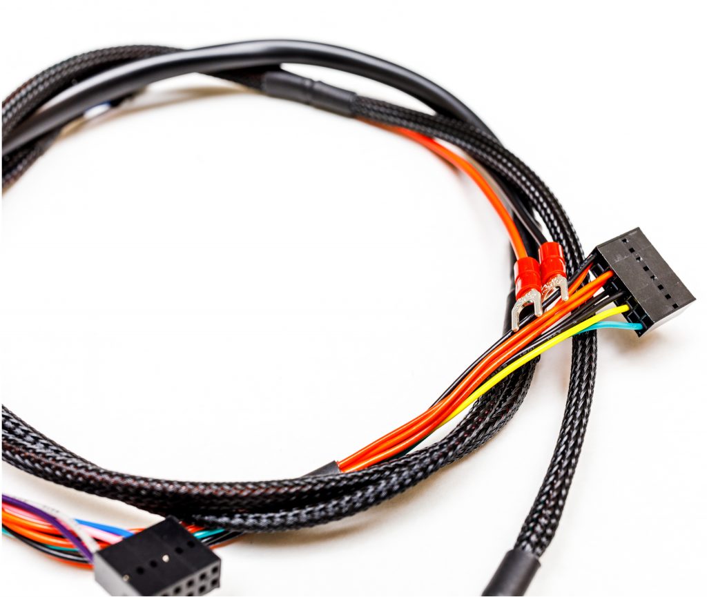
Outer Jacket Materials
Material selection affects flexibility, weight, chemical resistance, and operating temperature range. For instance, over 60% of industrial cables use PVC due to its low cost and decent durability, but extreme conditions require more specialized compounds like TPE or FEP, which can withstand temperatures from -55°C to 200°C and offer superior resistance to oils, solvents, and mechanical abrasion.
|
Material |
Temperature Range (°C) |
Relative Cost |
Flex Life (Cycles) |
Key Property |
|---|---|---|---|---|
|
PVC |
-20 to 105 |
1.0x |
10,000 |
Good all-rounder |
|
PUR |
-40 to 125 |
2.5x |
50,000 |
Excellent abrasion resistance |
|
TPE |
-50 to 135 |
1.8x |
25,000 |
High flexibility |
|
FEP |
-200 to 200 |
6.0x |
100,000 |
Highest temperature rating |
PVC (Polyvinyl Chloride) is the most common jacket material, making up roughly 60% of the market due to its low cost (approximately $0.50 per meter for a 4mm² cable) and decent versatility. It performs adequately in dry environments with temperatures between -20°C and 80°C. However, it becomes stiff below -10°C, increasing the risk of cracking during installation in cold weather. Standard PVC jackets have a flex life of around 10,000 bend cycles at a 5:1 bend radius before cracking occurs.
For higher durability applications, PUR (Polyurethane) is often selected. It costs about 2.5 times more than PVC but offers significantly better performance. Its key advantage is exceptional abrasion resistance—it can withstand over 500,000 cycles on a standard abrasion test machine, compared to just 50,000 for PVC. This makes it ideal for robotic cables in automated factories that undergo constant movement. PUR remains flexible down to -40°C and resists oils, solvents, and hydrolysis, making it suitable for wet environments like food processing or marine applications. Its typical operational lifespan in high-flex applications is 5–8 years, roughly double that of standard PVC.
TPE (Thermoplastic Elastomer) strikes a balance between performance and processability. It’s 80% more flexible than rigid PVC and doesn’t require vulcanization like rubber, reducing manufacturing time by 20%. TPE jackets maintain elasticity across a wider temperature range (-50°C to 135°C) and offer good resistance to weathering and ozone. They are often used in medical devices and consumer electronics where repeated flexing (25,000+ cycles) and a soft feel are required.
Connector Components
The connector is the critical interface of any cable assembly, responsible for over 70% of all system failures if specified incorrectly. Material selection, plating thickness, and mechanical design directly dictate current capacity, signal integrity, and mating cycle life. A standard industrial connector must withstand a minimum of 500 mating cycles while maintaining a contact resistance of less than 20 milliohms. The choice between brass, phosphor bronze, or beryllium copper for the contact pin, along with its plating—whether tin (1–3 µm), silver (2–4 µm), or gold (0.2–0.8 µm)—impacts both performance and cost by a factor of 10.
The fundamental trade-off in connector design is durability versus cost. For example, a phosphor bronze pin with a 0.2 µm gold flash over a 2 µm nickel underplate supports 1,000 mating cycles and 10 Gbps data rates, but increases the pin cost by 15% versus a standard tin-plated design.
Phosphor bronze (C51000) is the most common, offering a tensile strength of 600 MPa and good spring properties for ~5,000 mating cycles. For higher-cycle applications exceeding 10,000 insertions, beryllium copper (C17200) is preferred; it provides a tensile strength of 1,300 MPa and superior stress relaxation resistance, but costs 3x more than phosphor bronze. The pin’s current rating scales with its cross-sectional area; a 1.5 mm² pin can carry 5 amps continuously, while a 0.64 mm² pin is limited to 2 amps before exceeding a 30°C temperature rise.
Gold plating is the premium choice for low-voltage signals (< 48V) and high-reliability applications. A thin layer of 0.2 µm (microinches) is sufficient for 500 cycles in controlled environments, but 0.8 µm is required for 5,000 cycles in humid conditions (85% RH). The nickel underplate (1–3 µm) is critical to prevent zinc migration from brass bodies, which can cause fretting corrosion. For power applications above 10 amps, silver plating (4–8 µm) is more effective due to its lower contact resistance (0.5 milliohms vs. gold’s 2 milliohms) and higher current-carrying capacity, but it sulfides in polluted atmospheres. Tin plating (3–5 µm) is the most economical, suitable for up to 50 mating cycles, but its high friction coefficient requires 30% more insertion force and is prone to galling.
Shielding and Filling
Over 60% of data transmission errors in industrial settings stem from inadequate shielding, while proper filling compounds can extend cable lifespan by up to 40% in high-vibration environments. The selection between foil, braid, or composite shields, along with the use of fillers like PP or non-woven fabric, impacts performance across frequencies from 50 Hz to 10 GHz, with shielding effectiveness (SE) ranging from 40 dB to 120 dB.
-
Braided Shields: Typically made from tinned copper or silver-plated copper wires, offering 70–85% coverage and high durability.
-
Foil Shields: Utilize aluminum or polyester laminated foil, providing 100% coverage but lower mechanical strength.
-
Composite Shields: Combine braid and foil for coverage exceeding 90% and SE values above 100 dB.
-
Filling Materials: Include polypropylene (PP) yarn, non-woven fabric, or gel-based compounds to resist elongation and compression.
A standard braid uses 36–144 strands of tinned copper wire (0.10–0.15 mm diameter per strand) woven into a mesh with 70–85% coverage. This provides shielding effectiveness of 50–70 dB at 100 MHz, sufficient for most industrial power and control cables. The downside is weight: a 24 AWG cable with 85% copper braid adds ~25% to the overall mass. For higher flexibility, silver-plated copper braid improves conductivity by 5–8% and resists oxidation up to 150°C, but increases material cost by 30%. In dynamic applications like robotics, where cables undergo over 1 million flex cycles, a dense braid (≥80% coverage) reduces EMI-induced errors by 90% compared to unshielded designs.
Foil shielding excels in high-frequency applications where full coverage is critical. Aluminum-polyester laminate foil (0.05–0.08 mm thick) provides 100% coverage and delivers 70–90 dB of SE at 500 MHz–1 GHz, making it ideal for data cables (e.g., Cat6a, USB 3.0). However, foil is fragile—it tears under repeated bending (> 500 cycles at a 5d bend radius) and increases cable stiffness by 15%. To mitigate this, a drain wire (22–26 AWG tinned copper) is added for grounding, but improper termination can reduce SE by 20 dB. Foil shields are also susceptible to corrosion in high-humidity environments (> 80% RH), where moisture penetration can decrease SE by 10–15 dB over 2 years.
For extreme EMI environments (e.g., medical imaging, military radar), composite shielding is necessary. Combining a foil layer (100% coverage) with a 60–70% copper braid overlay achieves SE values exceeding 100 dB up to 10 GHz. This dual-layer approach adds 40% to material cost and 35% to cable diameter but reduces EMI-related data errors to < 0.001% in sensitive applications. The braid compensates for the foil’s mechanical fragility, enabling 1,000+ bend cycles without degradation.
Material Selection Factors
Over 60% of field failures trace back to incorrect material choices, while optimal selection can reduce total ownership costs by up to 30% over a 10-year lifecycle. Key drivers include operating temperature (-60°C to 250°C), mechanical stress (bend cycles from 1,000 to 10 million), chemical exposure, and regulatory standards (UL, ISO, RoHS). For example, a 15% upfront cost increase in material quality often yields a 200% improvement in mean time between failures (MTBF) in harsh environments.
-
Environmental Conditions: Temperature extremes, UV exposure, moisture, and chemical contact.
-
Mechanical Requirements: Flex cycles, tensile strength, abrasion resistance, and installation stress.
-
Electrical Performance: Voltage rating, impedance control, signal loss, and EMI shielding.
-
Cost vs. Lifespan: Initial material cost versus total cost of ownership over 5–20 years.
-
Compliance & Standards: UL, CE, RoHS, REACH, and industry-specific certifications.
For high-temperature applications above 150°C, FEP or PFA insulation is necessary, adding ~40% to material costs but enabling continuous operation at up to 250°C. In contrast, standard PVC jackets degrade rapidly above 105°C, with a lifespan of less than 1 year in such conditions. For UV exposure (e.g., solar farms, outdoor telecom), cross-linked polyethylene (XLPE) outperforms PVC, retaining 95% of its tensile strength after 10,000 hours of UV testing, while PVC drops to 50%. Chemical resistance is equally critical: in oil and gas applications, chloroprene rubber (CR) jackets withstand prolonged exposure to hydrocarbons, lasting 15+ years, whereas PUR shows signs of swelling after 5 years.
In automated machinery with continuous movement, cables endure up to 3 million bend cycles. Here, multi-stranded fine copper conductors (36+ strands per AWG) paired with TPE jackets reduce failure rates by 80% compared to standard 7-strand designs. Tensile strength matters during installation: aramid yarn fillers (e.g., Technora) provide 200 MPa tensile strength, allowing pull forces of 100 N/mm² without damaging conductors. For abrasion resistance, PUR jackets survive 500,000+ cycles on ISO 6722 testers, while PVC fails at 50,000 cycles.
|
Factor |
Standard Material |
High-Performance Alternative |
Cost Impact |
Lifespan Change |
|---|---|---|---|---|
|
High Temp |
PVC (105°C max) |
FEP (250°C max) |
+40% |
10x longer |
|
Oil Resistance |
PUR (moderate) |
Chloroprene Rubber (high) |
+25% |
3x longer |
|
Flex Cycles |
7-strand copper (10k cycles) |
36-strand copper (1M cycles) |
+30% |
100x longer |
|
Signal Integrity |
Solid PE (Dk 2.3) |
Foam PE (Dk 1.6) |
+20% |
N/A (performance gain) |
While CCA (copper-clad aluminum) saves 40% on initial material costs, its higher resistance leads to 20% more energy losses over 10 years, negating savings in high-power applications. Conversely, investing in gold-plated contacts (0.8 µm thickness) increases connector cost by 50% but reduces failure rates from 5% to 0.1% over 10,000 mating cycles. Compliance with RoHS and REACH restricts material options—halogen-free compounds (e.g., LSZH jackets) cost 25% more than PVC but are mandatory in public infrastructure, reducing toxic emissions by 100% in fire scenarios.
Harness cable assemblies integrate specialized materials: 22AWG tinned copper wires (stranded, 80% lay length) for conductivity, paired with PVC or TPU insulation (80–125°C rating). Outer jackets often use nylon 6.6 (600V rating, 100N abrasion resistance). Connectors feature brass nickel-plated shells (5μm coating thickness) and phosphor bronze contacts (80HV hardness). Shielding uses 85% braided tinned copper (EMI attenuation <30dB), while fillers like PTFE tape (–50°C to 200°C) stabilize bundles. Selection prioritizes voltage, environment, and mechanical stress.
