What's the Difference in Harness Assembly for EV vs. ICE
EV harnesses handle up to 800V with extensive shielding (90%+ coverage) and HVIL connectors for safety, while ICE versions focus on lower-voltage signals and power, using simpler, lighter materials.
High-Voltage System Differences
While a typical ICE vehicle uses a 12V or 48V low-voltage system to power accessories, an EV's main traction system operates at 300 to 800 volts, with some platforms pushing to 1000V. This high-voltage (HV) network is responsible for transferring energy from the battery to the inverter and then to the motor, handling continuous currents that can exceed 300 amps. This demands a completely different approach to wiring, focusing intensely on safety, insulation, and electromagnetic compatibility. The HV cables alone can account for a significant portion of the total harness cost, often 30-40% higher than the entire low-voltage system in an ICE vehicle, representing a major shift in component investment and design philosophy.
|
Feature |
ICE Vehicle |
Electric Vehicle (EV) |
|---|---|---|
|
Primary System Voltage |
12V or 48V |
300V to 800V (common), up to 1000V |
|
Key High-Voltage Cables |
Not Applicable |
Battery to Inverter, Inverter to Motor, DC-DC Converter |
|
Typical Conductor Size |
0.5 mm² to 6 mm² (low-voltage) |
16 mm² to 95 mm² (high-voltage) |
|
Primary Insulation Material |
PVC, Cross-linked Polyethylene |
Irradiated (Cross-linked) Polyethylene, Silicone Rubber |
|
Mandatory Safety Shield |
Often not required for LV circuits |
Always a metallic braid or foil shield |
|
Connector Locking |
Simple latches |
Complex mechanical and HV interlocks |
|
Visual Safety Coding |
Black or various colors |
Bright Orange (international standard for HV) |
The conductors themselves are massive, typically ranging from 35 mm² to 70 mm² for the main battery feed, which is over 10 times the cross-sectional area of a typical ICE battery cable. This size is necessary to minimize resistance and heat buildup under loads that can peak at 300 kW or more. The insulation isn't just thick plastic; it's a sophisticated layer of irradiated polyethylene or silicone rubber, designed to withstand temperatures from -40°C to 150°C and resist abrasion, chemicals, and coolant exposure.
A critical, non-negotiable component is the continuous 100% coverage shielding, usually a tinned copper braid. This shield contains the strong electromagnetic fields (EMF) generated by the high-frequency, high-current AC pulses in the cables, preventing interference with sensitive onboard electronics like sensors and control units. This shielding also acts as a first-line safety barrier. All HV connectors are a world apart from standard automotive parts. They feature two-stage locking mechanisms: a primary seal to keep out moisture and dust (rated at IP6K9K for high-pressure water jet resistance), and a secondary high-voltage interlock loop (HVIL). 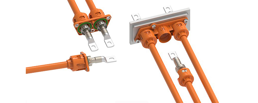
Wire Shielding and Safety
Unlike in ICE vehicles, where electromagnetic interference (EMI) is a minor concern, an EV's high-voltage cables carry rapidly switching currents at frequencies up to 20 kHz, acting like unintended radio transmitters. This EMI can cripple sensitive systems like the battery management system (BMS) and ADAS sensors, which operate on low-voltage signals with precision down to microvolts. Furthermore, the risk of a high-voltage leak is catastrophic. Consequently, EV wiring employs a multi-layered defensive strategy centered on advanced shielding, which can add 15-25% to the cost of a harness loop but is essential for vehicle operation and user safety.
|
Feature |
ICE Vehicle |
Electric Vehicle (EV) |
|---|---|---|
|
Primary Shielding Purpose |
Occasionally for data CAN bus lines |
Mandatory for all HV cables: Safety & EMI |
|
Common Shielding Type |
Foil shield (for some signals) |
Braided copper shield (≥85% coverage) |
|
Shield Connection |
Drain wire |
360-degree circumferential connector contact |
|
Dielectric Strength Test |
~1.5 kV for low-voltage wires |
>5 kV to 8 kV for 1 minute on HV components |
|
Leakage Current Tolerance |
Not a primary concern |
<0.5 mA during HV insulation testing |
The core design principle for EV shielding is creating a 100% continuous Faraday cage around every high-voltage conductor. Any gap, even a 1-2 mm misalignment in a connector, can become an exit point for EMI, reducing shielding effectiveness from a required ≥60 dB to a useless <20 dB.
The physical execution of this principle relies on a braided shield made from tinned copper wire, typically achieving 85% to 95% coverage density. This specific range is a cost/performance optimization; while 100% coverage is theoretically ideal, it adds excessive mass and cost for diminishing returns. The tin coating prevents oxidation, ensuring stable electrical performance over the vehicle's 15-year service life. This braid isn't just wrapped around the cable; it must be terminated with a 360-degree contact at every connector.
The entire HV system is subjected to rigorous dielectric testing, where 5,000 volts AC is applied for 60 seconds between the conductor and its shield to ensure no breakdown occurs, with leakage current monitored to stay below a strict 0.5 milliampere threshold. This is a stark contrast to ICE wiring, which might only be tested at 500-1,000 volts. Beyond EMI, the shielding also provides a critical secondary safety function. In the event of physical damage or a crash, the robust braid can act as the first point of contact for a short circuit, allowing the fuse or contactor to break the circuit within 100 milliseconds before energy escapes the contained system. The material cost for this shielding is significant, adding 8 per meter to the cable cost, but it is fundamental to making an EV both functional and safe.
Material and Weight Considerations
The 40-60% increase in total cable weight due to massive high-voltage conductors and the automotive industry's relentless pursuit of weight reduction to maximize driving range. Every extra kilogram of wiring can reduce an EV's range by approximately 1.5 to 2 kilometers, making material science a direct contributor to vehicle performance and efficiency. This has sparked a move away from traditional materials towards advanced, lightweight alternatives, even if they come at a higher initial cost per meter, as engineers perform a complex balancing act between mass, performance, durability, and total system cost.
While 99.9% of ICE vehicles use solid copper for its balance of conductivity and cost, many EV platforms are now adopting aluminum conductors for specific high-voltage runs. Aluminum has 60% of the conductivity of copper but is 70% lighter for the same volume. To carry the same current as a 50 mm² copper cable, you need an ~80 mm² aluminum cable; even with this 60% larger cross-section, the aluminum version is still ~40% lighter and 20-30% cheaper. The major trade-off is that aluminum is more brittle and prone to fatigue failure from vibration cycles over 10 years, requiring more sophisticated connector design with specialized crimps and anti-oxidation pastes to prevent a 30% increase in contact resistance over time.
For the critical insulation, irradiated cross-linked polyethylene (XLPE) is the dominant material, replacing standard PVC. XLPE offers a 50% higher operational temperature rating (150°C vs. 105°C) and superior resistance to coolants and abrasion, despite adding ~15% to the raw material cost. This allows the wires to be routed closer to heat sources like the motor, simplifying assembly and saving space. The shielding, a braided tinned copper mesh, adds substantial mass, often >250 kg/km. To mitigate this, some manufacturers are exploring thin-layer metallized polymer shields that can reduce shield weight by up to 50%, though this can compromise its durability during 20-year service life and effectiveness as a secondary safety barrier.
The pursuit of lightweighting even extends to the secondary retention systems. Denser, high-strength polymer conduit is replacing older corrugated tubing, saving ~100 grams per meter of run and providing a 30% improvement in crush resistance, which is critical for underbody protection against road debris. This entire material ecosystem is a calculated compromise, where a 5% increase in harness cost might be justified if it translates to a 15 kg overall weight reduction and a corresponding ~30 km extension in vehicle range.
Connector and Seal Variations
Where a typical ICE vehicle might use 50 to 100 primary connectors, a modern EV can easily exceed 150, with the high-voltage ones costing up to 50 times more than their low-voltage counterparts. This isn't just about connecting wires; it's about creating fail-safe, sealed systems that can handle extreme environments. The sealing and interlock mechanisms on these components are subjected to validation tests simulating over 15 years of use, ensuring they never become the weakest link in a high-voltage system where failure is not an option.
|
Feature |
ICE Vehicle Connector |
Electric Vehicle HV Connector |
|---|---|---|
|
Primary Sealing Method |
Single rubber seal (IP5X dust rating) |
Multiple silicone seals (IP6K7/IP6K9K rating) |
|
Locking Mechanism |
Plastic latch |
Two-stage mechanical & HV interlock (HVIL) |
|
Contact Material |
Tin-plated brass or copper |
Silver-plated copper (>3µm thickness) |
|
Pole Count & Size |
Up to 12 poles, ~2.8mm diameter |
2-6 large poles, 5mm to 12mm diameter |
|
Mating Force |
15-40 Newtons |
60-150 Newtons per connector |
|
Operating Voltage |
< 48V |
600V to 1000V+ |
|
Cost Range |
3.00 per connector |
150+ per connector |
Sealing and Environmental Protection: The ingress protection standard for an EV's high-voltage connector is IP6K7 (submersion proof) and IP6K9K (high-pressure, high-temperature jet proof), a world away from the basic dust and splash resistance (IP5X) common in ICE connectors. Achieving this requires at least two independent sealing barriers, typically made from silicone rubber for its wide temperature tolerance (-40°C to +180°C) and long-term elasticity. The first seal is often an axial face seal between the connector housings, while the second is a series of radial seals around each individual high-voltage pin. These seals are tested by being subjected to 80°C water at 1000-1500 kPa pressure for 30 minutes with zero leakage permitted.
High-Voltage Interlock Loop (HVIL): This is the primary active safety feature absent in all ICE vehicles. The HVIL is a low-current, low-voltage signal circuit that runs through a separate, tiny pin in the HV connector. Its electrical path is designed to be broken 50-100 milliseconds before the main high-voltage contacts are physically disconnected if someone tries to unplug the connector. This break in the circuit is detected by the vehicle's domain controller, which immediately commands the opening of the main battery contactors, safely isolating the high-voltage battery and discharging the system's capacitors to a safe voltage (< 60V) in under 1 second. The HVIL circuit must have a 99.99% reliability over the vehicle's life, with a failure rate of less than 1 in 10,000 operations.
Contacts and Performance: The electrical contacts themselves are massively scaled up. Instead of handling 15 amps maximum, they are designed for continuous currents of 250-400 amps. To handle this without excessive resistance heating (< 2 milliohms per contact), the pins are much larger (5-12mm diameter) and are silver-plated to a thickness of 2-4 micrometers instead of tin. Silver offers lower and more stable contact resistance, which is critical for minimizing power losses (I²R losses) that could generate dangerous heat at high currents. The physical mating force for these large, tight-fitting connectors is significant, often requiring over 60 Newtons of force to fully engage, ensuring a gas-tight connection that won't vibrate loose.
Automation in Assembly
Where a traditional ICE harness might require 20-30 hours of manual labor for cutting, stripping, crimping, and inserting wires into connectors, the complexity and safety-critical nature of EV harnesses is making full automation an economic necessity. The driving forces are clear:
-
Precision Requirements: Robotic systems achieve a pin insertion accuracy of ±0.05 mm, eliminating the ~5% damage rate common in manual assembly of high-pin-count connectors.
-
Cost of Error: A single mis-crimped HV connector can cause a $15,000 battery pack failure, far outweighing the initial investment in automation.
-
Volume Scaling: Automated lines can produce a complete 60 kg EV main harness in under 3 hours, a task that would take a 20-person manual line over 8 hours.
Manual assembly of a 95 mm² cable with a large silver-plated terminal is physically demanding and prone to variability; an operator might achieve a consistent crimp 19 out of 20 times. In contrast, a fully automated robotic crimping station uses 1000 Hz real-time force-and-distance monitoring to adjust the crimp profile for every single terminal, ensuring a 0-defect outcome and a pull-off force that varies by less than ±2%.This is critical because a 10% increase in resistance at a connection handling 300 amps can generate 90 watts of excess heat, creating a major fire risk.
Every harness now undergoes a 100% electrical test on a automated test rig that applies 2500 volts for 60 seconds to check insulation resistance, measures each pin's resistance to the micro-ohm level, and functionally tests the HVIL circuit by simulating disconnects in under 50 milliseconds. This comprehensive testing, which adds ~15 minutes per harness, is impossible to perform manually at production volumes of 300,000 units per year. The return on investment for automation is calculated not just in labor savings, which can reduce direct assembly cost by 40-60%, but in warranty cost avoidance.
An automated line with machine vision can inspect every seal and connector lock, reducing field failure rates from ~500 defects per million (DPM) in manual lines to <10 DPM. While the capital expenditure for a fully automated line can range from 7 million, the payback period for a high-volume EV program is typically under 24 months due to the combined effects of higher yield, lower labor costs, and vastly improved quality and safety.
Testing and Validation Methods
This process can consume 15-20% of the total harness development budget and involves subjecting components to stresses simulating over 15 years of service life in a condensed 6 to 9-month testing cycle. The goal is to achieve a failure rate of less than <10 defects per million (DPM), a standard that demands extreme precision and leaves no room for error.
-
In-Line Electrical Testing: Every single connector and circuit is verified for continuity, resistance, and short circuits.
-
Dielectric Withstanding (Hi-Pot) Test: A non-negotiable high-voltage stress test for all components.
-
Environmental Stress Testing: Simulating years of vibration, thermal cycling, and fluid exposure.
-
HVIL Functional Validation: Ensuring the critical safety interlock operates within a strict time window.
Automated test rigs perform a 100% electrical test on every harness. This isn't just a simple continuity check; it measures contact resistance at each terminal to a precision of < 5 milliohms to identify any imperfect crimps that could cause overheating. Immediately after, the high-potential (Hi-Pot) test is applied. For low-voltage circuits, this might be 500-1000 V DC. For the high-voltage system, ≥ 2500 V AC (or ≥ 5000 V DC) is applied between all live parts and the shield for 60 seconds, while monitoring leakage current. Any leakage exceeding 0.5 mA results in immediate rejection.
|
Test Category |
ICE Vehicle Standard |
Electric Vehicle (EV) Standard |
|---|---|---|
|
Dielectric Strength |
500 V - 1,000 V for 60 sec |
2,500 V AC / 5,000 V DC for 60 sec |
|
Insulation Resistance |
> 10 MΩ at 500 V DC |
> 100 MΩ at 1000 V DC |
|
Vibration Test |
10 Hz - 500 Hz, 2 hrs per axis |
5 Hz - 2000 Hz, 8 hrs per axis, 3 axes |
|
Thermal Cycling |
-40°C to 85°C, 500 cycles |
-40°C to 150°C, 1000+ cycles |
|
Fluid Resistance |
Water, fuel |
Water, coolant, battery acid, 240hrs+ |
|
HVIL Response Time |
Not Applicable |
< 100 milliseconds to break signal |
Vibration testing on 3-axis shakers runs for 8 hours per axis using a profile tailored to the vehicle's motor and road frequencies (5 Hz to 2000 Hz), a test that is 400% longer and more intense than typical ICE validation. Thermal cycling chambers rapidly move harnesses from -40°C to +150°C for over 1000 cycles to test the integrity of seals, materials, and the stability of electrical properties.Connectors are immersed in glycol-based coolant at 85°C for 1000 hours to ensure the seals prevent any fluid ingress that could cause a short. The HVIL circuit is functionally tested by triggering a disconnect and verifying the vehicle's main contactors open and the system is discharged to a safe voltage in under 100 ms.
This analysis highlights key differences in harness assembly, where EVs require handling 600V+ systems with robust shielding for 100dB EMI attenuation. Lightweight materials like aluminum are adopted, saving up to 30% weight, and IP67-rated sealed connectors are mandatory. Automation and rigorous high-potential testing at 1000V+ ensure safety and reliability.
