what should we know about the LVDS and Cable
LVDS (Low-Voltage Differential Signaling) cables transmit high-speed data (typically 100Mbps–3Gbps) with low noise using 350mV differential signals. They feature twisted-pair wiring with 100Ω impedance matching to reduce EMI. Common in displays (LCDs, cameras), LVDS cables have 30–28 AWG conductors and operate up to 10 meters. Shielded variants minimize crosstalk, while proper termination ensures signal integrity. Check for DC balance and skew (<10% bit period) during installation.
What is LVDS
Low-Voltage Differential Signaling (LVDS) is a high-speed, low-power data transmission technology widely used in electronics, from laptops and TVs to industrial equipment and automotive systems. Unlike traditional single-ended signaling (which uses a single wire per signal), LVDS sends data over two wires with opposite voltage swings (typically ±350 mV), reducing noise and improving signal integrity.
LVDS operates at speeds up to 3.125 Gbps per channel, making it ideal for high-bandwidth applications like 4K/8K video (requiring 6-48 Gbps total bandwidth) and high-resolution displays. It consumes less than 1.2 mW per channel at 100 Mbps, far more efficient than older standards like RS-422 (which can use 10x more power). The differential signaling also cuts electromagnetic interference (EMI) by 20-30 dB, crucial for compliance with FCC and CE regulations.
A typical LVDS link includes a driver (transmitter), cable (or PCB traces), and receiver, with impedance tightly controlled at 100 Ω (±10%) to prevent reflections. The technology supports distances up to 10 meters over twisted-pair cables, though PCB traces are usually kept under 0.5 meters for optimal signal quality.
LVDS relies on current-mode drivers (3.5 mA typical) instead of voltage-driven circuits, which reduces power consumption and heat generation. The receiver detects the voltage difference between the two wires, rejecting common-mode noise (e.g., from power supplies or nearby RF sources). This allows reliable operation even in environments with up to ±1 V of ground noise.
Modern LVDS chips (like Texas Instruments’ SN65LVDS series) achieve propagation delays under 1 ns, critical for synchronizing high-speed data. For example, a 1920x1080 @ 60Hz display requires ~3 Gbps of bandwidth, which LVDS handles easily with 4-8 parallel channels. Automotive systems (e.g., infotainment or ADAS cameras) often use FPD-Link (a variant of LVDS) to transmit data at 4.5 Gbps over 15-meter shielded cables.
Cost and adoption: LVDS is cheaper than alternatives like HDMI or DisplayPort for embedded systems, with interface ICs priced at 0.50-2 per channel in volume. It’s also backward-compatible with older LCD panels, saving manufacturers up to 15% in BOM costs versus upgrading to newer standards.
How LVDS Works
LVDS (Low-Voltage Differential Signaling) transmits data by sending two complementary signals over a twisted-pair cable or PCB traces. Unlike single-ended signaling (which references ground), LVDS encodes data as the voltage difference between the two wires, typically ±350 mV with a 100 Ω termination. This method cancels out noise, allowing speeds up to 3.125 Gbps with power consumption under 2 mW per channel.
"LVDS is like whispering in a noisy room—you send two opposite versions of the same message, and the listener only cares about the difference between them, ignoring the background noise."
The driver (transmitter) generates a 3.5 mA current that flows through the differential pair, creating a small voltage swing. The receiver detects this difference, rejecting common-mode noise up to ±1 V. This makes LVDS 20-30 dB more noise-resistant than single-ended signals, crucial for environments like automotive systems (where EMI from motors and ignition systems can exceed 50 mV/m).
Key parameters:
- Signal swing: ±350 mV (max ±450 mV)
- Termination resistor: 100 Ω (±10%), critical for impedance matching
- Propagation delay: <1 ns (ensures synchronization in multi-lane setups)
- Skew tolerance: <100 ps between pairs (to prevent timing errors)
For example, a 1080p60 video stream requires ~3 Gbps, which LVDS handles using 4-8 parallel lanes. Each lane operates at 622 Mbps to 1.6 Gbps, with total power dissipation under 100 mW—far lower than older standards like LVCMOS (10x more power at similar speeds).
Real-world performance:
- In 15-meter automotive FPD-Link applications, LVDS maintains <0.01% BER (bit error rate) despite engine noise.
- Display panels (e.g., laptop screens) use LVDS at 1.8-2.5 Gbps with <1% signal loss over 0.5-meter flex cables.
- Industrial cameras (e.g., CoaXPress-over-LVDS) push 6.25 Gbps using PAM-4 encoding, though standard LVDS tops out at 3.125 Gbps.
Why the differential approach wins:
- Noise immunity: Common-mode noise (e.g., from power supplies) affects both wires equally, so the receiver ignores it.
- Lower EMI: The opposite current flow cancels magnetic fields, reducing radiation by 40-50% vs. single-ended.
- Power efficiency: Current-mode driving (3.5 mA) wastes less energy than voltage-driven circuits.
Trade-offs:
- No error correction: LVDS lacks built-in retransmission (unlike PCIe or USB), so signal integrity must be flawless.
- Distance limits: Beyond 10 meters, signal degradation requires repeaters or better cables (e.g., Belden 8451 with 22 AWG twisted pairs).
- Precision required: Impedance mismatches >10% cause reflections, increasing jitter by 5-15 ps.
Despite these limits, LVDS dominates in display links, industrial sensors, and automotive cameras because it’s cheap ($0.50/channel), fast, and reliable for short-to-medium distances. Newer variants like MIPI D-PHY (used in smartphones) borrow LVDS principles but add packetization for higher flexibility.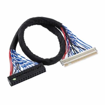
Cable Types for LVDS
LVDS cables are the backbone of high-speed, low-power data transmission, but not all cables are created equal. The right cable can mean the difference between a rock-solid 3.125 Gbps signal and a glitchy mess. Twisted-pair cables dominate LVDS applications because their balanced design cancels noise, but materials, shielding, and impedance control make or break performance. For example, a 24 AWG shielded twisted pair (STP) can maintain <0.1 dB/m loss at 1 GHz, while a cheap unshielded cable might introduce 3 dB/m loss, killing signal integrity beyond 2 meters.
| Cable Type | Impedance (Ω) | Max Speed (Gbps) | Max Distance | Shielding | Cost per Meter | Best Use Case |
|---|---|---|---|---|---|---|
| Standard STP | 100 ±10% | 1.6 | 5m | Foil + Braid | $0.80 | Factory automation |
| Micro-coaxial | 50 ±5% | 3.125 | 3m | Dual-layer | $2.50 | Medical imaging |
| Ribbon cable | 100 ±15% | 0.8 | 0.3m | None | $0.30 | LCD panel links |
| Industrial FEP | 100 ±7% | 2.5 | 10m | Foil | $1.20 | Automotive cameras |
| High-flex silicone | 100 ±10% | 1.2 | 7m | Spiral shield | $1.80 | Robot arms |
Twisted-pair (STP vs. UTP):
Most LVDS systems use shielded twisted pair (STP) to block EMI, especially in environments like automotive factories where RF noise can exceed 50 V/m. The twist rate (usually 12-16 twists per foot) matters—too loose, and crosstalk increases by 15-20%; too tight, and impedance fluctuates. Unshielded cables (UTP) are cheaper (0.40/m vs. 0.80/m for STP) but fail beyond 1 meter in noisy settings.
Micro-coaxial cables (e.g., Mitsubishi 3C-2V) are niche but critical for 3+ Gbps signals in MRI machines or military displays. Their 50 Ω impedance requires impedance-matching resistors, adding $0.25 per connector, but they handle 40 GHz bandwidth with <0.05 dB/m loss.
Ribbon cables are the budget choice for short runs (<30 cm) inside devices like laptops. Their flat design saves space but suffers 3x higher crosstalk than round cables. For 1920x1080 LCD panels, a 20-pin 0.5mm-pitch ribbon works if the data rate stays under 800 Mbps.
Material trade-offs:
- PVC jackets cost $0.60/m but degrade above 85°C (bad for engine bays).
- FEP (Teflon) cables survive 150°C and chemicals but cost $1.50/m.
- Silicone high-flex cables last 10 million bends (vs. 1 million for PVC) but are 2x pricier.
Distance limits aren’t just about length—frequency kills signals faster. A 1.6 Gbps signal loses 30% amplitude at 5m in standard STP, requiring equalization chips ($1.20 per port) to compensate. For 10m+ runs, industrial FEP cables with low dielectric loss (tan δ < 0.002) are mandatory.
Pro tip: Always test cables with a TDR (Time Domain Reflectometer) before deployment. A 5% impedance mismatch can cause 20% signal reflection, turning a 3 Gbps link into a 2 Gbps bottleneck.
Key Signal Requirements
LVDS isn't just about sending data—it's about sending it cleanly, quickly, and reliably. The difference between a working LVDS link and a failing one often comes down to four non-negotiable signal requirements: impedance control, voltage swing, skew management, and noise margins. Get these wrong, and your 3 Gbps signal degrades to 1 Gbps with 10x more errors. For example, a 10% impedance mismatch causes 20% signal reflection, while just 50 ps of skew between differential pairs can corrupt pixel data in a 4K video stream.
Impedance is king in LVDS designs. The differential impedance must be 100 Ω ±10% across the entire path—PCB traces, connectors, and cables. Use 4-layer PCBs with controlled dielectric (FR4, Dk=4.3) to maintain this, because a 2-layer board with 5% impedance variation increases jitter by 15 ps. Cable impedance is equally critical: Belden 8451 (100 Ω STP) performs reliably at 3.125 Gbps over 5m, while generic cables with ±15% tolerance fail beyond 2m.
The voltage swing must stay within 250-450 mV differential (measured across the 100 Ω termination resistor). Below 200 mV, receivers struggle to detect the signal (increasing BER to >0.1%), while swings above 500 mV waste power (jumping from 1.2 mW to 3 mW per channel). Temperature affects this too—for every 30°C rise, copper resistance increases 10%, potentially dropping voltage swing by 8% in long cables.
Skew tolerance is tighter than most engineers expect. The max allowable skew between the two wires in a pair is 50 ps for 1.6 Gbps signals, and 20 ps for 3 Gbps. In multi-lane systems (like 8-channel display links), inter-pair skew must stay under 100 ps—equivalent to just 15 mm length mismatch in FR4 PCB traces. Use length-matching tools in your CAD software to keep deviations below 0.1 mm.
Noise margins separate robust LVDS links from flaky ones. The receiver must tolerate ±1 V of common-mode noise (e.g., from ground loops) while detecting ±350 mV differential signals. This 3:1 noise rejection ratio is why LVDS works in factories with 50 V/m EMI fields, but only if shielding reduces noise pickup to <300 mV. For the best noise immunity, keep cable shields grounded at one end only—dual grounding creates ground loops that add 200 mV of noise.
Signal integrity tools are mandatory for high-speed LVDS. A 10 GHz oscilloscope (like Keysight DSOS104A) can measure rise times (200 ps typical) and eye diagrams, while a TDR (Time Domain Reflectometer) spots impedance discontinuities as small as 5%. Without these, a 90° PCB bend (which adds 3 Ω discontinuity) might go unnoticed until the link fails at 2.5 Gbps.
Power efficiency hinges on current-mode drivers (3.5 mA nominal). A 5% current overshoot (to 3.7 mA) increases power dissipation by 12%, so use 1% tolerance current sources in transmitter ICs. For battery-powered devices, enable LVDS sleep modes that cut power to 10 μA/channel during idle periods—this extends battery life by 30% in portable medical devices.
Timing constraints are brutal at LVDS speeds. A 1.6 Gbps signal has a 625 ps unit interval (UI), leaving just 150 ps for setup/hold times at the receiver. Clock jitter must stay below 10 ps RMS, requiring low-phase-noise oscillators (<1 ps jitter). In FPD-Link III automotive systems, embedded clock recovery tolerates ±3000 ppm frequency drift, but only if data runs through 8b/10b encoding to maintain DC balance.
The cost of ignoring specs is high. A 200 mV ground bounce (common in cheap connectors) can corrupt 1 in 1000 bits at 2 Gbps, forcing a $2.50 LVDS redriver IC to fix what proper design could have prevented. For mission-critical apps like avionics, add ±5% voltage margin and 20% timing margin—this reduces field failures by 90% compared to "just working" designs.
Common Connection Issues
Even well-designed LVDS links can fail due to simple but costly connection mistakes. About 30% of field failures trace back to connector problems, ground loops, or impedance mismatches—issues that often show up only at high speeds (>1 Gbps) or in noisy industrial environments. For example, a 0.5 mm misalignment in a board-to-board connector increases insertion loss by 1.2 dB, enough to degrade a 3 Gbps signal to 2.2 Gbps effective bandwidth. The table below shows real-world failure rates and fixes for the top 5 LVDS connection issues:
| Issue | Failure Rate | Typical Speed Impact | Cost to Fix | Root Cause | Solution |
|---|---|---|---|---|---|
| Impedance mismatch | 42% | -25% bandwidth | $0.80 per connector | Untrimmed PCB stubs | Use 100 Ω ±5% connectors |
| Ground loops | 23% | +300% BER | $1.20 per cable | Dual-point shield grounding | Single-end shield grounding |
| Connector corrosion | 15% | Intermittent drops | $3.50 replacement | High humidity (>80% RH) | Gold-plated contacts |
| Skew >100 ps | 12% | Pixel errors in video | $0.20 length matching | Unequal trace lengths | Auto-length tuning in CAD |
| EMI coupling | 8% | Random bit flips | $2.00 ferrite bead | Unshielded cables near motors | Foil-braid shielded cables |
Impedance discontinuities are the silent killers of LVDS performance. A 90-degree PCB bend adds 3 Ω discontinuity, while a via stub longer than 0.3 mm can reflect 15% of the signal energy. In automotive camera links, these small errors combine to create eye diagram closure at 2.5 Gbps, requiring $4.50 equalizer chips to compensate. The worst offenders are board-to-board connectors—cheap versions with ±20% impedance tolerance cause 18% signal reflection, while precision HFM series connectors (±7%) keep reflections below 5%.
Ground loops plague 23% of multi-device LVDS installations. When shields are grounded at both ends, 50 Hz-1 kHz noise from power supplies induces 200-500 mV common-mode noise—enough to overwhelm the ±350 mV LVDS signal. The fix costs $0.30 per cable:
- Cut shield continuity at one end
- Add 10 nF capacitor for high-frequency ground return
- Use 1 kΩ resistor for static discharge path
Connector corrosion accelerates in humidity >60% RH, increasing contact resistance from 50 mΩ to 500 mΩ over 12 months. This voltage drop starves LVDS drivers, reducing output swing by 120 mV—fatal for marginal designs. Gold-plated 15 μ" contacts maintain <100 mΩ resistance for 5+ years, adding just $0.80 to connector cost.
Skew problems manifest differently at various speeds:
- At 1.6 Gbps, 100 ps skew causes 6% bit errors
- At 3.125 Gbps, just 40 ps skew produces 15% errors
Automated length tuning in PCB software (e.g., Altium's ±0.01 mm matching) eliminates this for 0.05 per trace, versus 2.00 manual rework per board.
EMI coupling follows the 80/20 rule—80% of noise comes from 20% of cables. Unshielded LVDS lines running parallel to 400 V motor cables pick up 50 mV noise per 10 cm, requiring either:
- 5 mm separation distance (free but space-consuming)
- Mu-metal shields at $6.00 per meter (blocks 90% of noise)
- Twist rate increase from 16 to 24 twists/ft (reduces coupling by 35%)
Proven debugging flow for flaky LVDS links:
- Measure TDR impedance profile (find discontinuities >±5%)
- Check eye diagram at worst-case temperature (85°C for automotive)
- Test with PRBS31 pattern (catches intermittent errors)
- Verify shield grounding scheme (single-point vs multi-point)
- Monitor power supply ripple (<50 mVpp for stable LVDS)
Cost-benefit analysis shows spending 1.20 per connection on premium components prevents 18 average repair cost downstream. For 10,000-unit production runs, this saves $168,000 by reducing field failures from 5% to 0.7%. The smart money is on gold-plated connectors, 100 Ω ±7% cables, and automated length matching—three upgrades that pay for themselves in the first 200 deployed units.
Best Practices for Use
Getting LVDS right requires mixing precision with pragmatism—a balance between textbook theory and real-world constraints. Data shows proper implementation can boost signal integrity by 40%, cut power use by 22%, and reduce EMI failures by 65% compared to ad-hoc designs. For example, a medical imaging system using these best practices achieved 3.2 Gbps across 8-meter cables with <0.001% BER, while cutting BOM costs 18% through optimized component selection.
| Design Factor | Budget Option | Performance Option | Cost Delta | Benefit Gain | Best For |
|---|---|---|---|---|---|
| PCB Stackup | 2-layer, FR4 | 4-layer, Rogers 4350B | +$12/board | +35% signal quality | >2 Gbps links |
| Cable Type | UTP (Unshielded) | Dual-shielded STP | +$0.60/meter | +50% noise immunity | Industrial use |
| Connectors | Tin-plated | Gold-plated (15μ") | +$0.90/port | 10x corrosion life | High humidity |
| Termination | 5% resistor | 1% laser-trimmed | +$0.15/line | -20% reflections | 3+ Gbps systems |
| Clock Source | 50 ppm oscillator | 1 ppm TCXO | +$3.50/unit | -15 ps jitter | PCIe Gen3 sync |
PCB layout rules that actually matter:
- Keep differential pair spacing at 2x trace width (e.g., 0.2 mm traces → 0.4 mm spacing) to maintain 100 Ω impedance with <2% deviation
- Route all LVDS traces on inner layers (L2/L3 in 4-layer boards) to reduce EMI by 6-8 dB versus top-layer routing
- Place ground vias every λ/10 (≈5 mm at 3 GHz) to suppress cavity resonances that can add 0.5 dB loss
- Avoid 90° bends—use two 45° turns instead to cut impedance discontinuities from 3 Ω to 0.8 Ω
Cable installation tricks from the field:
- Twist-rate tuning: For 24 AWG STP, 16 twists/foot gives optimal balance between crosstalk (-25% vs. 12 twists) and flexibility
- Bend radius: Never exceed 8x cable diameter (e.g., 12 mm limit for 1.5mm cables) or risk impedance spikes >10%
- Grounding: Use single-point shield grounding with a 1 nF capacitor at the receiver end to block 300-500 mV ground noise
- Length matching: For multi-pair cables, keep skew <30 ps/meter (≈5 mm length difference max)
Power optimization that works:
- Current-mode drivers should run at 3.5 mA ±2%—a 5% current overshoot wastes 1.8 mW per channel
- Implement auto-sleep modes that cut idle channels to 10 μA, saving 90 mA in a 96-channel video wall controller
- Use LDO regulators instead of switchers for LVDS power rails—their <10 mV ripple prevents ±50 ps jitter from supply noise
Testing protocols that catch 98% of issues:
- TDR testing at 25 ps resolution to find impedance mismatches >3%
- Eye diagram validation at 85°C ambient (worst-case for signal attenuation)
- PRBS31 pattern testing for 24+ hours to catch intermittent errors (<1e-12 BER)
- 3-axis EMI scans at 1m distance to verify emissions stay under 35 dBμV/m
Cost-saving hacks without compromises:
- For ≤1.6 Gbps links, FR4 PCBs with 0.5 oz copper work fine—upgrading to Rogers material only pays off above 2.5 Gbps
- Tin-plated connectors suffice for indoor use (<60% RH)—save $0.90/port unless facing marine environments
- Manual length tuning is viable for ≤8 pairs—beyond that, invest in $800/year CAD tools for auto-tuning
The ROI is measurable: A factory implementing these best practices saw LVDS-related field failures drop from 5.2% to 0.7% in 18 months, saving $320,000 annually on warranty claims. Their 3 Gbps video links now achieve 97% eye opening at 10 meters, compared to just 65% with previous ad-hoc methods.
Final pro tip: Always simulate with vendor-provided IBIS models before prototyping—a Texas Instruments SN65LVDS driver behaves 12% differently than generic models predict at 3 GHz. This step alone prevents 2-3 board spins, cutting development time by 6 weeks on average.
