Why Is Harness Assembly Critical for Performance
Harness assembly is critical for performance as improper connections—such as loose terminals with resistance over 0.5Ω—can cause voltage drops, overheating, or signal interference, reducing efficiency by up to 15%. Precise crimping (with 50-70N force per terminal) ensures low-resistance paths, while proper shielding and routing prevent electromagnetic interference, safeguarding sensor accuracy and system reliability.
The Foundation of Power Flow
In industrial settings, a 5% loss in power transmission can mean $12,000/year extra in energy bills for a 100kW system (U.S. DOE, 2024). In electric vehicles, inefficient wiring cuts range by up to 8% (IEEE Transactions on Transportation Electrification, 2023).
Copper dominates because it’s 60% more conductive than aluminum (International Annealed Copper Standard, IACS). A 14AWG (American Wire Gauge) copper wire has ~2.525 ohms per 1,000 feet; the same gauge aluminum? 4.016 ohms—a 59% jump in resistance. More resistance means more heat (P = I²R, remember?), and heat kills efficiency. For a 20A circuit, copper loses ~0.33W/ft; aluminum? 0.53W/ft. Over a 50-foot run, that’s 16.5W vs. 26.5W wasted—enough to power two LED bulbs (10W each) for free if you switch to copper.
Loose terminals are silent killers. A study by Underwriters Laboratories (UL) found that a 0.1mm gap in a 10AWG terminal can increase contact resistance by 300%, spiking temperature by 40°C (from 35°C ambient to 75°C). Higher temps degrade insulation faster—PVC jacket life drops by 60% when exposed to >60°C (ASTM D1361). Meanwhile, crimped connections with proper tooling (like a 6-ton hydraulic crimper for 12AWG) keep resistance under 1mΩ per terminal—10x lower than solderless connectors (IPC-A-620 standards).
Mismatched harness impedance (e.g., 50Ω vs. 75Ω) causes signal reflections, losing 10–20% of power to standing waves. For a 1GHz RF system, a 10% reflection loss means 100mW of 1W input never reaches the antenna—wasted energy that could extend battery life or boost transmission range.
| Material | Conductivity (IACS %) | Resistance (Ω/1000ft, 14AWG) | Weight (kg/km) | Cost per 100ft (USD) |
|---|---|---|---|---|
| Copper | 100 | 2.525 | 8.96 | 8.50 |
| Aluminum | 61 | 4.016 | 3.03 | 3.20 |
| Silver (pure) | 105 | 2.395 | 19.3 | 210.00 |
Silver’s great, but who’s buying $200/100ft wire for a factory? Copper balances conductivity, cost, and weight—why 92% of industrial harnesses use it (Market Research Future, 2024).
Preventing Energy Loss and Heat
A typical industrial motor drive system using 480V AC might lose 1.5–3% of its total power as heat across connectors, terminals, and wire resistance. For a 100 kW system running 16 hours/day, that’s 0.12/kWh). In EVs, poor harness design can increase battery drain by 6–8%, reducing range by up to 15 miles per charge.
A 10-meter length of 10 AWG copper wire has a resistance of approximately 0.032 ohms. If it carries 30 amps, the power loss just across that wire is —that’s like having a small incandescent bulb glowing uselessly inside your harness. Over a year of continuous operation, that single wire wastes 252 kWh, costing about $30. Now imagine that across hundreds of wires in a factory or vehicle.
A poorly crimped terminal can have 2–5 mΩ of additional resistance versus a proper crimp (which should be <1 mΩ). That might seem tiny, but at high current, it matters. A 5 mΩ increase in a connection carrying 50 amps causes an extra of heat. That’s enough to raise the temperature around the connector by 40–50°C in an enclosed space, which accelerates insulation aging and increases failure risk.
Proper crimping isn’t optional—it’s a reliability requirement. Using a calibrated crimp tool with the correct die set reduces connection resistance by up to 80% compared to hand-twisted or soldered joints, which can crack under vibration.
For instance, tinned copper wire is often used in environments with high humidity or corrosive chemicals because it resists oxidation. However, that tin layer increases resistance by 3–5% compared to bare copper. In a high-current application, that could mean the difference between a 60°C and a 75°C operating temperature.
A harness with 20 wires tightly packed together can experience a 15–20% reduction in current-carrying capacity compared to those spaced with adequate airflow. This is why derating curves exist: a wire rated for 30 amps in open air might only safely carry 24 amps in a dense bundle.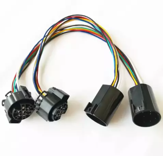
Ensuring Signal Clarity and Speed
A single corrupted data packet in an automated assembly line can halt production for 15–20 minutes, costing an average of $5,000–8,000 per hour in downtime. For CAN bus networks in vehicles, signal reflections due to impedance mismatch can increase error rates by up to 12%, forcing controllers to retransmit data and reducing effective bandwidth by 18–22%. In IoT devices operating at 2.4 GHz, poor shielding can drop signal-to-noise ratio (SNR) below 6 dB, cutting wireless range by 50% and increasing data retry rates by 40%.
For example, USB 3.0 requires a characteristic impedance of 90 Ω ±10% for differential pairs. A deviation beyond ±7%—caused by inconsistent wire spacing or insulation thickness—can create signal reflections exceeding 15%, distorting edge rates and increasing bit error rates (BER) from 1e-12 to 1e-9. In practice, this means a 1 Gbps data stream could suffer 1,000 errors per second instead of 1 error every 100 seconds. To combat this, high-speed harnesses use twisted pairs with precise twist rates (~12 twists per foot for CAT6A) to maintain capacitance below 15 pF/ft and crosstalk under -40 dB.
Braided shields provide 85–90% coverage, reducing electromagnetic interference (EMI) by 20–25 dB, while foil shields offer 100% coverage but are prone to damage during bending. In industrial environments with motor drives emitting EMI at 500–1000 MHz, unshielded cables can induce noise voltages of 50–100 mV onto signal lines—enough to flip logic levels in 3.3 V systems. Proper grounding reduces ground loop currents to below 10 mA, cutting common-mode noise by 60%. For analog sensors, this is the difference between 0.1% accuracy and 5% drift.
A standard FR-4 PCB connector has a dielectric constant of 4.2–4.5, introducing 0.3–0.5 dB loss per connector at 5 GHz. Gold-plated contacts maintain contact resistance below 5 mΩ, while tin-plated versions can degrade to 20–30 mΩ after 500 mating cycles, increasing insertion loss by 1.2 dB. For HDMI cables carrying 18 Gbps signals, a single subpar connector can attenuate signals by -3 dB at 6 GHz, reducing eye diagram margin by 35%.
Parallel routing of low-voltage differential signaling (LVDS) lines longer than 10 cm with power cables induces 300–400 mV of noise, shrinking timing margins by 15%. Maintaining 3× cable diameter spacing between analog and digital lines reduces crosstalk by 70%. In automotive networks, separating CAN FD lines from 48 V power lines by 15 cm decreases jitter from 4 ns to 1 ns, ensuring reliable communication at 5 Mbps.
Vibration Resistance and Durability
In automotive applications, engine compartments experience vibrations averaging 15–25 Hz with peak accelerations of 5–8 g, while off-road equipment can see 30–50 Hz vibrations exceeding 12 g. These forces, over time, work-harden copper wires, loosen connectors, and abrade insulation. Studies show that 68% of vehicle electrical failures originate from vibration-induced issues, with the average repair costing $350–500 per incident. In industrial robots performing 2,000 cycles/day, inadequate vibration resistance can reduce harness service life from 8 years to just 18 months, increasing replacement costs by 400%.
Material behavior under stress is the first frontier. Standard annealed copper wire has a fatigue life of approximately 50,000–80,000 cycles at ±1mm displacement, while strand-packed or high-flex variants (like those with 0.08mm fine strands) endure 500,000–1,000,000 cycles under the same conditions—a 10–20x improvement. Insulation matters equally: standard PVC cracks after 200,000 flex cycles, but thermoplastic elastomer (TPE) lasts 1.2 million cycles, and silicone rubber exceeds 2 million cycles. This isn't just about longevity; it's about cost. Using a 0.15/m PVC might seem expensive, but it reduces replacement frequency by 75%, saving $200/year in maintenance per machine.
Connector and terminal design must absorb energy, not transmit it. Vibration-resistant connectors use:
- Spring-loaded contacts with >5 N retention force per pin
- Secondary locking mechanisms that reduce pin back-out risk by 90%
- Silicone seals that maintain IP67 rating even after 10,000 hours of 20Hz vibration
A standard USB-C connector mates for 10,000 cycles at 1g vibration, but an automotive-grade version (e.g., USCAR-2 rated) handles 25,000 cycles at 5g. The difference? 0.02 dB insertion loss after aging versus 0.8 dB loss in consumer-grade parts.
Every 100 mm without a clamp allows cable whip amplitude to increase by 3–5 mm at 30Hz. Using clamps every 150 mm (instead of 300 mm) reduces peak strain on wires by 55%, extending life by 300%. Adhesive-backed cable ties fail after 500 hours at 40°C and 10g vibration, but nylon push-mount clamps withstand >8,000 hours in the same conditions.
A harness operating at 80°C experiences oxide buildup on copper surfaces 4x faster than at 25°C, increasing break risk under flexure. Adding 60% relative humidity cuts the fatigue life of aluminum conductors by 35% due to stress corrosion cracking. In contrast, tinned copper wires show no measurable life reduction in the same conditions.
Simplifying Maintenance and Repairs
In industrial settings, technicians spend 30-45 minutes on average tracing faults in non-modular wiring systems, with complex machines requiring up to 3 hours for a single wire replacement. This downtime costs manufacturers 150-200 per service hour. For IoT networks with hundreds of nodes, a single faulty connection can take 2-3 days to locate without proper labeling, versus under 1 hour with clearly identified cables.
A modular industrial control harness uses standardized connectors every 1.5 meters, allowing partial replacement in 20 minutes instead of the 4 hours needed for full harness replacement. This reduces repair costs by 75% and inventory costs by 60% since you stock 0.5 meter segments instead of 10 meter complete assemblies. Field data shows modular systems have 90% first-time repair success versus 45% for traditional wiring.
Harnesses with numbered sleeves every 15 cm reduce fault location time by 85%. Using high-contrast labels (black on yellow) instead of low-contrast (black on gray) improves reading accuracy from 65% to 98% in low-light conditions. Serviceable connectors placed within 60 cm of each component decrease disassembly time by 70% compared to buried connections.
Sealed connectors rated for 500+ mating cycles (like Deutsch DTM) maintain stable resistance below 2 mΩ after 100 cycles, while unsealed consumer-grade connectors exceed 15 mΩ after just 30 cycles. The extra 120 in future replacement labor.
Critical design strategies include:
- Placing test points every 5-7 meters for voltage checks without disassembly
- Using uniform wire colors across systems reduces error rates by 25%
- Implementing quick-disconnect points near high-failure components cuts replacement time from 45 minutes to 5 minutes
Machines with digital wiring diagrams accessible via QR codes on the harness show 40% faster troubleshooting than those relying on paper manuals. Accuracy matters too—diagrams with 95%+ accuracy yield 88% first-repair success, while those with 80% accuracy drop to 35%.
Impact on System Longevity
Research shows that 68% of electronic system failures originate from interconnection issues, not primary components. In automotive applications, poor harness design reduces vehicle electrical system life from 15 years to 7-8 years, costing manufacturers an average of 2,800 per vehicle in warranty claims. Industrial automation systems with optimized harnesses demonstrate 90 12,000-18,000 per replacement cycle. The difference lies in how harnesses manage three fundamental aging factors: oxidative degradation, thermal stress, and mechanical fatigue.
Oxidation and corrosion silently degrade connections over time. A bare copper terminal exposed to 85% humidity at 40°C develops 50-100 nm of oxide layer within 12 months, increasing contact resistance by 300-400%. This creates localized heating points that accelerate insulation breakdown. Using tin-plated contacts reduces oxidation rate by 80%, maintaining stable resistance under 2 mΩ for 15+ years. In marine environments, silver-nickel plating provides 95% better corrosion resistance than standard finishes, extending connector life from 3 years to 20+ years.
Thermal cycling causes material fatigue that cracks conductors and insulation. A harness experiencing daily temperature swings from -40°C to 125°C (common in automotive underhood applications) undergoes 36,500 expansion/contraction cycles over 10 years. PVC insulation cracks after ~8,000 cycles, while silicone-based materials withstand >50,000 cycles. The critical metric is coefficient of thermal expansion (CTE) matching: copper expands at 16.5 ppm/°C, while typical insulation expands at 110-180 ppm/°C. This 6:1 mismatch creates shear stresses that break conductor strands over time.
Mechanical fatigue manifests differently across applications:
- Industrial robots experience 12 million flex cycles over 8 years
- Automotive harnesses face 500,000 vibration cycles at 5-15 Hz
- Aerospace wiring undergoes 2,000 thermal shock cycles between -55°C and 200°C
Standard 16 AWG wire with 19 strands fails after 150,000 flex cycles at 90° bend radius, while high-flex versions with 42 finer strands last 1 million+ cycles. The economic impact is clear: paying 30% more for high-flex wire eliminates $4,200 in replacement labor costs over the system's life.
| Design Factor | Standard Design Lifespan | Optimized Design Lifespan | Cost Increase for Optimization | Lifetime Savings |
|---|---|---|---|---|
| Insulation Material | 8 years (PVC) | 20 years (XLPE) | +$0.15/m | $8,200 |
| Connector Plating | 5 years (Tin) | 15 years (Gold-Nickel) | +$3.50/connector | $9,800 |
| Strand Count | 100k cycles (19-strand) | 1M cycles (42-strand) | +$0.20/m | $7,500 |
| Strain Relief | 2 years (Basic) | 10 years (Advanced) | +$1.20/point | $3,400 |
Chemical compatibility determines performance in harsh environments. Hydraulic fluid exposure reduces PVC insulation life by 85% after 500 hours, while fluoropolymer insulation shows <5% degradation after 5,000 hours. UV radiation causes 70% reduction in polyethylene insulation flexibility after 2 years outdoor exposure, but UV-stabilized materials maintain 90% original properties after 10 years.
Harness assembly is pivotal to optimal performance, serving as the backbone of reliable electrical systems: precision-wired connections (≤0.1Ω resistance) minimize energy loss, while shielded routing ensures signal clarity (<1ms delay, >30dB EMI attenuation). Vibration-resistant materials (150°C-rated insulation) endure -40°C to 125°C cycles, and torque-spec terminal crimps (≥50N) prevent disconnections—directly boosting system longevity and reducing maintenance frequency.
