Wire Harness Assembly Process | 6 Key Steps Explained
The wire harness assembly process begins with design and prototyping, followed by cutting and stripping wires to precise lengths. Wires are then fitted with terminals and connectors, often using automated machinery for large batches, before being assembled onto a board. The harness undergoes rigorous electrical testing and final inspection before shipment.
Planning and Design First
Rushing into production without a detailed schematic and layout can lead to a 15-30% increase in material waste from incorrect wire lengths and a up to 50% longer assembly time due to constant rework and confusion. In contrast, investing time in a meticulous design phase can reduce overall project costs by up to 20% by optimizing material use and streamlining installation.
The planning phase begins with the schematic diagram, which is the functional roadmap of the entire electrical system. It details every connection, specifying the exact wire gauge (e.g., 20 AWG for signal lines vs. 10 AWG for high-current applications drawing 30 amps), component parameters (like a 100Ω resistor with a 5% tolerance), and the specific pin-to-pin connectivity. A single error here can render an entire batch of harnesses useless. Modern design almost exclusively relies on ECAD (Electronic Computer-Aided Design) software like Zuken E3.series or Mentor Capital to create these schematics digitally. This allows for automatic generation of wire lists and connection reports, drastically reducing human error from manual transcription.
Following the schematic, the physical layout is created. This defines the harness's real-world form factor, bend radii, and routing paths. A key deliverable from this stage is the 2D formboard drawing, which is a 1:1 scale diagram that assembly technicians will use as a physical template to build the harness on. This drawing must account for bundle diameters—a group of 15 wires might form a bundle with a 10mm outer diameter, requiring a specific size of conduit or sleeve. It also specifies the minimum bend radius, which for many cables should be no less than 10 times the outer diameter to prevent internal conductor damage.
Furthermore, the layout determines the precise location of every clamp, tie-wrap, and grommet, ensuring the harness will fit perfectly within its intended enclosure without putting stress on the connections. For a complex harness in an industrial machine, this process can take 40-60 hours of engineering time, but it prevents thousands of dollars in field failures and installation delays.
Selecting the Right Wires
A wire that is too thin for a 15-amp load can experience a temperature rise of over 30°C above ambient, increasing resistance and creating a potential fire hazard. Conversely, overspecifying wire gauge can inflate harness weight by up to 40% and material costs by 25%, making a project uncompetitive. This selection process is a precise balance of electrical requirements, environmental conditions, and cost constraints, not a generic choice.
The core decision revolves around three interconnected parameters: current load (amps), wire gauge (AWG), and insulation rating. The goal is to select the smallest acceptable gauge that can safely carry the required current without exceeding its temperature rating. For example, a common 18 AWG wire with PVC insulation is typically rated for ~10 amps in chassis wiring, but the same gauge in a high-temperature environment (105°C vs. 80°C) might have a 15% higher current capacity. Voltage drop over distance is another critical, often overlooked, factor. A 14 AWG wire carrying 10 amps over a 10-meter (32.8 ft) run will have a negligible drop of about 0.5 volts in a 12V system. However, the same current through a thinner 20 AWG wire over the same distance would result in a ~2-volt drop, which could be enough to prevent a motor or sensor from operating correctly.
Beyond electrical specs, the operating environment dictates insulation and jacketing material. A harness in an engine bay must withstand temperatures exceeding 125°C (257°F) and exposure to oils, requiring materials like cross-linked polyethylene (XLPE) or silicone. For abrasion resistance in a robotic arm that flexes 500,000+ times in its lifespan, a thermoplastic elastomer (TPE) jacket is superior to standard PVC.
|
Application |
Typical Current Load |
Recommended Wire Gauge (AWG) |
Insulation Type |
Key Environmental Consideration |
|---|---|---|---|---|
|
Automotive Signal Wiring |
< 5 amps |
20 - 22 |
PVC |
Temperature range: -40°C to 85°C |
|
12V DC Power (e.g., solar) |
10 - 20 amps |
12 - 14 |
XLPE or PVC |
UV resistance, outdoor durability |
|
Industrial Motor Power (480V AC) |
30 - 50 amps |
8 - 10 |
Ethylene Propylene Rubber (EPR) |
High temperature (90°C+), oil resistance |
|
Internal Device Wiring |
1 - 3 amps |
24 - 26 |
Teflon (PTFE) |
Tight spaces, high heat (105°C+) |
Always consult the American Wire Gauge (AWG) standard and manufacturer datasheets for precise ampacity charts. The initial cost difference between a standard PVC wire and a specialized Teflon-insulated one can be 1.00 per meter.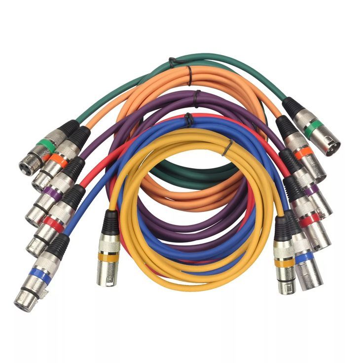
Cutting and Stripping Wires
Inaccurate wire lengths can cause up to 15% material waste on a large project, while improper stripping can nick conductors, reducing current-carrying capacity by over 20% and creating future failure points. A clean, accurately stripped wire ensures a perfect crimp or solder connection, which is fundamental to the harness's electrical integrity and long-term performance. This stage is where the design plan becomes physical reality.
The process begins with cutting wires to the exact length specified in the design documentation. Using automated cutting machines for production runs is far more efficient than manual methods; a bench-top cutter can process over 1,200 wires per hour with a length tolerance of ±1 mm (±0.04 inches), compared to roughly 200-300 wires per hour manually with a tolerance of ±5 mm (±0.2 inches). For a batch of 10,000 wires, this efficiency gain saves over 30 hours of labor. The machine's blade life is typically 50,000 to 100,000 cuts before needing replacement, a cost that must be factored into the operational budget.
Stripping is the critical step of removing 3-5 mm (0.12-0.2 in) of insulation from the wire end without damaging the delicate copper strands beneath. The stripping depth must be calibrated to within ±0.1 mm (±0.004 in) of the insulation's thickness. A common error is setting the stripper blades too deep, which nicks or severs 5-10% of the strands. This reduces the wire's effective cross-sectional area; a nicked 16 AWG wire might perform like an 18 AWG wire, potentially overheating under its intended 10-13 amp load. Thermal strippers are excellent for fine gauges (28-24 AWG), melting the insulation cleanly without pressure, while laser stripping offers the highest precision for expensive, high-density cables.
|
Wire Gauge (AWG) |
Typical Insulation Thickness (mm) |
Recommended Strip Length (mm) |
Tolerance (±mm) |
Tool Type (Manual) |
Tool Type (Production) |
|---|---|---|---|---|---|
|
22-24 (Signal) |
0.5 - 0.7 |
3.0 |
0.2 |
Precision Hand Stripper |
Automated Rotary Blades |
|
18-20 (General) |
0.8 - 1.0 |
4.0 |
0.3 |
Self-Adjusting Stripper |
Automated Blade & Laser |
|
12-14 (Power) |
1.2 - 1.5 |
5.0 - 6.0 |
0.5 |
Heavy-Duty Stripper |
Programmable Blade Machine |
|
8-10 (High Power) |
1.5 - 2.0 |
7.0 - 8.0 |
0.8 |
Kinetic Energy (Wire-Break) |
Hydraulic Strip & Crimp Unit |
Always measure strip length from the end of the wire, not from the insulation. A quality strip leaves all conductor strands intact and undamaged. For a large operation, investing 15,000 in a semi-automatic strip machine pays for itself in less than 12 months by reducing scrap rates from 5% to under 0.5% and drastically improving connection reliability. This step cannot be rushed; its accuracy defines the quality of every termination that follows.
Arranging and Grouping Wires
Properly arranging and grouping wires into a coherent bundle reduces installation time by up to 40%, minimizes the risk of connection errors during assembly by over 60%, and critically, prevents electromagnetic interference (EMI) that can corrupt sensitive signal data. A well-organized harness with a clear routing path is easier to handle, often reducing its installed physical volume by 15-20% within an enclosure, which is crucial in space-constrained applications like robotics or avionics.
The process starts on a formboard, following the 1:1 layout diagram. Wires are cut to length and laid out precisely according to the design. The first rule of grouping is to separate power and signal lines. Bundling a 120V AC power cable carrying 10 amps next to a low-voltage 0-5V sensor signal wire is a recipe for induced noise, potentially creating a ±500 mV error in the reading. Instead, maintain a minimum separation of 50 mm (2 inches) between such cable types. For critical analog or high-speed digital signals (e.g., CAN bus, Ethernet), using twisted pairs or shielded cables within the bundle is non-negotiable.
The second rule involves managing bundle diameter and bend radius. As wires are grouped, their combined diameter increases. A bundle of twenty 20 AWG wires has a diameter of approximately 6-8 mm. You must select a conduit or sleeve with an internal diameter (ID) at least 25% larger than the bundle's outer diameter to allow for easy pulling and to avoid crushing. Furthermore, the entire bundle must respect the minimum bend radius, which is typically 10 times the overall bundle diameter. Forcing a tighter bend stresses all wires and connectors simultaneously.
Pro Tip from the Field: Always route wires at a 90-degree angle to any sharp edges or corners on a chassis. Use a 3 mm thick adhesive-backed rubber grommet to protect the bundle if it must pass through a metal panel. This single step prevents more than 80% of field failures related to insulation wear and short circuits over a 5-year product lifespan.
Grouping is also about serviceability. Using different colored cable ties (e.g., blue for data, yellow for power) or applying numbered marker sleeves every 150-300 mm along the bundle drastically reduces the time a technician needs to locate a specific circuit.
For a complex harness containing 150+ wires, this simple labeling practice can cut diagnostic time from 30 minutes to under 5 minutes. The goal is to create a logical, robust, and serviceable assembly that translates the schematic into a physical reality without error.
Securing with Ties and Sleeves
A wire harness is only as reliable as its weakest point of support. Vibration and movement can quickly degrade unsecured wiring, with studies showing that 60% of premature harness failures originate from abrasion or fatigue at improper attachment points. Using the correct tie and sleeve for the environment can increase the harness's operational lifespan by over 200%, from just 2 years to over 6 years in a high-vibration setting like an agricultural vehicle. This step transforms a grouped bundle into a single, robust assembly ready for installation.
The selection of securing hardware is critical and depends on three factors: environment, temperature, and required tensile strength.
-
Nylon Cable Ties (Standard Duty): The most common choice for benign environments. A standard 4.8 mm wide x 200 mm long tie has a min. loop tensile strength of 18 kg (40 lbs) and is rated for temperatures from -40°C to 85°C. They are cost-effective, costing 0.05 per unit in bulk. However, they become brittle and lose up to 50% of their strength when continuously exposed to UV light or temperatures above 85°C.
-
Stainless Steel Zip Ties (Heavy Duty): Essential for high-temperature or highly corrosive environments like engine bays or chemical plants. They can withstand temperatures exceeding 400°C (752°F) and have a tensile strength of over 90 kg (200 lbs). Their cost is significantly higher, at 1.50 per unit, but they are a permanent solution.
-
Heat-Shrink Tubing (Sealing & Bundling): Used to create sealed, professional endpoints on bundles or to provide abrasion resistance at specific points. Polyolefin tubing shrinks to roughly 50% of its original diameter when heated to 120°C (248°F) with a heat gun. For a 3 mm diameter bundle, a 6 mm diameter tube is selected. It provides excellent strain relief and environmental protection.
-
Braided Sleeving (Abrasion & EMI Protection): Typically made from PET (polyester) or fiberglass, this expandable sleeving protects against sharp edges and high temperatures. A 10 mm diameter sleeve can expand to accommodate a bundle up to 20 mm in diameter. It can handle continuous temperatures of up to 150°C (302°F).
Placement is governed by strict rules. Ties should be spaced every 150-300 mm (6-12 inches) along a horizontal run. This prevents the harness from sagging more than 5 mm per 100 mm of length. Near any connection point, a tie must be placed within 50 mm (2 inches) of the connector body to prevent mechanical stress from being transferred to the terminals. When tightening, use a dedicated tensioning tool to achieve a consistent 20-25 lbs of pull force; overtightening with pliers can crush insulation and reduce the bundle's diameter by over 15%, damaging wires. The tail of any tie must be trimmed to within 2-3 mm of the head to prevent injury from sharp edges. This meticulous approach to securing ensures the harness will survive a decade of service.
Final Inspection and Testing
A single wiring error that slips through can cause a 30-40% increase in field service costs and damage brand reputation. A comprehensive final check, which typically adds only 5-8% to the total assembly time, catches over 99% of faults before the harness leaves the facility. This phase validates the entire assembly process, ensuring electrical integrity, mechanical robustness, and perfect adherence to the customer's specifications.
The inspection and testing protocol is a multi-stage process that leaves no room for assumptions.
-
Visual and Dimensional Inspection (100% of harnesses): This first pass checks for obvious physical defects. Inspectors verify that the harness length is within ±10 mm of the design specification and that the bundle diameter does not exceed the maximum allowed by 15%. They check that every connector is present and correctly keyed, and that 100% of cable ties are properly trimmed with no sharp edges. They also confirm that all labeling and markings are legible and correctly positioned within 50 mm of each connector.
-
Continuity Testing (100% of harnesses): Using a multichannel continuity tester, technicians verify that every intended electrical path has a low-resistance connection (typically < 1 Ohm) and that no unintended short circuits exist between pins (resistance > 10 MOhm). A modern tester can check a harness with 150 circuits in under 60 seconds, logging results for traceability. This test immediately identifies miswires, broken strands, and crushed cables.
-
Hi-Pot (Dielectric Withstanding Voltage) Test (Sample or 100%): This safety-critical test stresses the insulation. For a harness rated for 250V AC operation, a test voltage of 1500V AC is applied for 60 seconds between all conductors and the harness shield or ground. The leakage current must remain below a threshold, usually < 5 mA. Any insulation flaw, thin spot, or contamination will cause a breakdown, preventing a potential safety hazard.
-
Insulation Resistance Test (Sample): This test measures the quality of the insulation under a DC voltage, typically 500V DC. A good harness will show an insulation resistance value exceeding 100 MOhm at 25°C and 50% humidity. A reading below 10 MOhm often indicates moisture contamination or degraded insulation material.
Investing 25,000 in a semi-automatic test station pays for itself within 6-18 months by reducing warranty claims by up to 90% and eliminating the cost of reworking harnesses after they have been fully assembled. The final sign-off is a data-driven decision, not a guess, ensuring every delivered harness performs flawlessly for its entire 10-15 year service life.
In summary, the wire harness assembly is a meticulous, multi-stage process. It begins with critical planning and design using software like CAD to create a schematic. Wires are then precisely cut to length, stripped, and often terminated with connectors. The individual components are arranged on a assembly board (or formboard) according to the design, grouped and secured with cable ties, lacing, or sleeving for protection. The process culminates in a rigorous final inspection and testing, including continuity and hipot tests, to ensure 100% quality and functionality before shipment.
