Wire Harness Connector Types | 5 Most Common Varieties
Common wire harness connectors include Molex Micro-Fit 39-01-2040 (40-pin, 0.8mm pitch, automotive, 3A/contact), Amphenol ARINC 600 (1553B bus, 75Ω impedance, aerospace, IP68-rated), TE DEUTSCH DT (IP67, -40°C to +125°C, commercial vehicles, 20-pin max), JST SH (1mm pitch, 0.5A/contact, consumer electronics, crimp-lock design), and Hirose FH12 (100-pin, 0.5mm pitch, medical devices, 0.2mm insertion force per pin).
Rectangular: Multi-Pin and Housing
In fact, a 2024 Electronics Components Report found they hold a 32% share of the global connector market, outpacing circular and board-to-board types due to their modular design. Why? Because their rectangular shape lets engineers stack pins in tight rows—critical when you need to route 10, 20, or even 100+ signals (power, data, ground) through a single interface. Take consumer electronics: a mid-range laptop uses 8–12 rectangular connectors internally, each with 15–40 pins, to link the motherboard to displays, batteries, and USB ports. In automotive, that number jumps: a single EV battery pack relies on rectangular connectors with 50–200 pins to connect cells, sensors, and cooling systems.
Multi-pin connectors live or die by their contact design. Most use either stamped-and-formed (S&F) or machined contacts. S&F pins, made by stamping flat metal sheets into shapes, dominate cost-sensitive apps (e.g., consumer gadgets). They cost ~$0.02 per pin at scale but max out at 2.5A per pin (vs. machined pins’ 5A). Machined pins, cut from solid brass, handle higher currents—think power tools or industrial motors—but cost 3–5x more.
Pin spacing is another make-or-break spec. Tighter spacing (e.g., 1.27mm) lets you fit more pins in a smaller housing, but it risks short circuits if debris gets in. Loose spacing (5.08mm, common in industrial gear) is rugged but bulky. The sweet spot? 2.54mm (0.1 inch)—the “standard” pitch used in 60% of industrial control connectors. It balances density (up to 40 pins per row) with EMI shielding; a 2023 test by Connector Tech Magazine found 2.54mm-pitch connectors block 92% of radio interference at 1GHz, vs. 78% for 1.27mm.
| Material | Max Temp (°C) | Vibration Resistance (g) | Typical Use Case | Cost Premium Over Plastic |
|---|---|---|---|---|
| Polycarbonate | 125 | 5–10 | Consumer electronics (laptops) | — |
| Nylon 6/6 | 105 | 10–15 | Industrial enclosures | +15% |
| PBT (glass-filled) | 150 | 15–20 | Automotive under-hood | +30% |
| Aluminum Alloy | 200+ | 20–30 | High-vibration (construction) | +100% |
Take polycarbonate: cheap ($0.50 per housing for 10-pin connectors) but melts at 125°C—bad news for EV chargers, which run hot. Aluminum housings, though pricier, handle 200°C+ and survive drops onto concrete (tested to 1.5m drop height per IEC 60529). For waterproofing, many housings add gaskets or O-rings. An IP67-rated connector (submersible to 1m for 30min) costs 2x more than an IP54 (dust-tight, splashes-resistant) model, but in marine or food processing, that 2x spend prevents 10k+ in downtime from corrosion.
Circular: Sealed and Threaded
They dominate sectors like automotive, aerospace, and industrial automation, accounting for approximately 28% of all connector sales in heavy machinery applications. A typical mid-range agricultural vehicle, for instance, uses 15–25 circular connectors across its systems, from sensor arrays on harvesting equipment to hydraulic control units.
| Feature | IP67 Rating | IP68 Rating | IP69K Rating |
|---|---|---|---|
| Test Pressure | 10–20 kPa | 100–300 kPa | 8–10 MPa |
| Immersion Depth/Time | 1m for 30 mins | >1m (specified) | High-pressure jets |
| Typical Cost Premium | Baseline | +15% | +30% |
| Common Use Cases | Outdoor signage, washdown areas | Submersible sensors, deep well pumps | Food processing, chemical cleaning |
An IP67-rated connector (ingress protection code) can withstand immersion in 1 meter of water for 30 minutes at room temperature. This is achieved through a combination of silicone or rubber grommets at the cable entry point and a primary seal, usually a silicone O-ring with a shore hardness of 50A–70A, compressed between the plug and socket housings. For more extreme conditions, IP68 and IP69K come into play. IP68 allows for continuous submersion, often at greater depths—3 meters for 24 hours is a common manufacturer specification. IP69K, however, is designed to resist high-pressure, high-temperature washdowns. It must survive water jets at 80°C, 8–10 MPa pressure, from a 0.3m distance. This is non-negotiable in food and beverage plants, where equipment is cleaned with 80–95°C caustic solutions daily.
Most industrial circular connectors use a metric thread, like M8, M12, or M23, with the number denoting the outer diameter of the threads. The M12 form factor is the undisputed workhorse, making up an estimated 60% of all circular connectors sold for factory automation sensors and actuators. The coupling nut typically requires a 90° to 180° rotation to achieve a secure mate, generating >5 Nm of torque for a proper seal on larger M23+ designs. This mechanical advantage creates a consistent, high-force interface for the contacts, reducing contact resistance to <5 milliohms. This is critical for power transmission; a poor mate increases resistance, generating heat (P=I²R losses). For a 10A load, a bad connection with 20 milliohms of resistance would waste 2W of power as heat, potentially raising the connector’s temperature 15–20°C above ambient.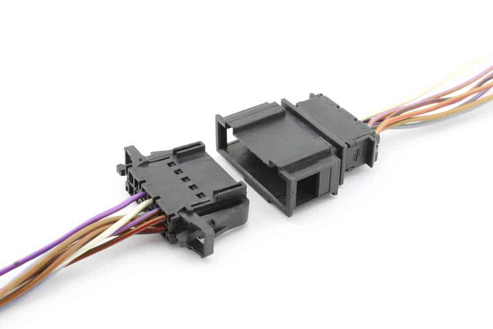
Board-to-Board: Stacking and Pin Header
A typical smartphone uses 8–12 distinct BTB connections to interface its main board with sub-assemblies like the display, camera module, battery, and buttons. The global market for these connectors is projected to reach $8.5 billion by 2027, driven by the demand for smaller, more powerful devices. Their performance hinges on two core concepts: the stacking height that defines the gap between boards and the pin header system that makes the actual connection. Getting this wrong doesn't just cause failure; it wastes precious millimeters in a device that might only be 7mm thick.
Most headers use a phosphor bronze contact, plated with 0.4–0.8 µm of gold over 1.0–2.0 µm of nickel for corrosion resistance and stable low resistance. The contact resistance is typically <20 milliohms, which is critical for power delivery. For a 5A power rail, a poor connection could generate 0.5W of heat (P = I²R), enough to raise local temperature by 20–30°C in a sealed device. The plastic housing, usually LCP (Liquid Crystal Polymer) or PBT, must have a high heat deflection temperature; LCP survives 260°C reflow soldering cycles without warping, while cheaper Nylon alternatives soften at 150°C. The choice here directly impacts manufacturing yield; a housing that warps during soldering causes 0.5–1.0% misalignment defects in high-volume production.
Stacking Height: This is the vertical distance between the two connected PCBs, measured from the board surface to the top of the mated connector. It is not a single number but a range defined by the connector's design and the required clearance for components on the inner board surfaces.
- Common Heights: Standard heights range from 0.5mm (for ultra-thin stacked memory modules) to 20mm (for industrial control boards with large capacitors and heat sinks underneath).
- Tolerance: The specified height has a typical manufacturing tolerance of ±0.05mm to ±0.10mm. This stack-up error must be accounted for in the mechanical design to avoid putting stress on the solder joints.
- Cost vs. Height: Achieving a lower profile costs more. A standard 3.0mm height connector pair may cost 0.80–$1.20 due to tighter machining tolerances and specialized materials.
For a drone's flight controller, a designer might stack a sensor board 4mm above the main CPU using a 40-pin, 0.8mm pitch header. This connector must survive 15g of vibration and have a mating cycle life of at least 50 connects/disconnects for factory testing. The 0.8mm pitch allows for 40 signals in a 32mm² footprint, but it requires a PCB trace width of 0.1mm and impedance control within ±10%, adding $0.02 per square cm to the board's fabrication cost. Conversely, an industrial PLC module can use a rugged 5.08mm pitch header with a 10mm stacking height. This header costs 30% less, can carry 3A per pin, and is rated for >500 mating cycles, but it consumes 400% more board area. The choice is never just about the connector; it's about the system-wide trade-off between density, robustness, and total cost.
Wire-to-Board: Crimp and IDC Types
They are the single most common connection point in low-voltage assembly, with an estimated 45 billion units shipped annually for use in appliances, automotive interiors, and industrial control panels. A modern car, for instance, uses over 300 WTB connections in its cabin alone for features like power seats, window controls, and infotainment systems. The choice between the two dominant technologies—crimp and insulation displacement contact (IDC)—is a fundamental decision that impacts manufacturing speed, long-term reliability, and total installed cost. This isn't a minor detail; selecting the wrong type can add 30,000 for a production run of 100,000 units.
A proper crimp for a 22 AWG wire must withstand a >50 Newton (N) pull force and exhibit a resistance of <2 milliohms. This is achieved with precision tooling; a semi-automatic crimping press costing 8,000 can process 1,200 terminations per hour with a defect rate of <0.1%. The terminals themselves are typically phosphor bronze and cost 0.030 each. The main advantage of crimping is its application range: it can handle wire sizes from 30 AWG (0.05 mm²) up to 12 AWG (3.3 mm²) and currents from signal-level 0.5A up to 25A for power connections.
IDC (Insulation Displacement Contact): This technology eliminates the wire stripping step, saving significant time and cost. A sharp, fork-like contact is pressed onto the insulated wire, piercing through the plastic and making direct contact with the conductor inside.
- Insertion Force: The process requires a precise 40–80 Newtons of force per wire. Too little force causes an unreliable connection (resistance can spike to >20 milliohms); too much force can damage the contact or the PCB.
- Cost & Speed: IDC terminals are cheaper at 0.015 per position. More importantly, an automated IDC press can terminate a 10-conductor ribbon cable in under 3 seconds, achieving rates of over 5,000 connections per hour.
- Limitations: IDC is best suited for smaller, standardized wire gauges, primarily 26 AWG to 20 AWG (0.14–0.5mm²), and is generally limited to signals under 3A. The insulation material must also be compatible; harder fluoropolymer insulation can be difficult to pierce reliably.
The upfront tooling cost is justified by the versatility, even with a slower assembly rate of 400–600 connections per hour. For a high-volume printer manufacturer running 1 million units a year, standardizing on a 20-conductor 28 AWG ribbon cable with IDC connections is a clear win. The 120,000 in direct costs alone. The reliability under vibration also differs; a well-executed crimp can withstand >15g of vibration, while an IDC connection is typically rated for 7–10g, making crimp the default for automotive and aerospace applications where vibration is a primary design concern.
RF Connectors: Impedance and Bayonet Style
RF (Radio Frequency) connectors are specialized components designed to carry high-frequency signals with minimal loss and reflection, forming the critical link in systems where signal integrity is paramount. They are ubiquitous in telecommunications, with a typical 5G base station utilizing 24–32 RF connections for its antenna arrays and transceivers. The global RF connector market is valued at over $5 billion, driven by the rollout of high-bandwidth networks and satellite communications. Unlike standard connectors, their performance is dominated by two non-negotiable characteristics: controlled impedance for signal preservation and a secure coupling mechanism—often a bayonet style—to maintain that performance under real-world stress. A poor RF connection in a 6 GHz Wi-Fi router can attenuate the signal by 3 dB, effectively cutting its range and throughput in half.
The absolute cornerstone of any RF connector is its characteristic impedance, almost universally standardized at 50 ohms (75 ohms for video broadcast). This isn't a suggestion; it's a requirement for minimizing signal reflection, quantified as Voltage Standing Wave Ratio (VSWR). A perfect connection has a VSWR of 1:1, but in practice, a quality connector maintains <1.2:1 VSWR up to 6 GHz. This is achieved through precise mechanical engineering: the diameter of the center pin, the insulation material's dielectric constant, and the outer shell's inner diameter must be held to tolerances of ±0.02mm. For example, an SMA connector's center pin must be 0.51mm in diameter with a concentricity tolerance of <0.05mm to the outer shell to ensure consistent 50-ohm impedance. Using a cheaper, out-of-spec connector can increase VSWR to 1.5:1 or higher, reflecting 4% of the transmitted power back towards the source. For a 100W radar system, that means 4W of power is wasted as heat at the connection point, potentially overheating the interface and degrading the semiconductor amplifier behind it.
The bayonet coupling mechanism, exemplified by the widespread BNC connector, is the industry's answer to the need for a quick, reliable, and vibration-resistant mate. The connector is mated by aligning and pushing the plug into the jack, then rotating the coupling nut ~90 degrees. This action engages a pin in a spiral slot, mechanically locking the connection with a consistent >20 Newtons of retention force. This design allows for a secure connection in under 2 seconds, a critical feature for test and measurement equipment where probes might be connected and disconnected hundreds of times a day. The bayonet lock is exceptionally resistant to vibration; a properly engaged BNC can withstand >10g of vibration across a 10–2000 Hz frequency range without disconnecting or causing an intermittent signal. This makes it the default choice for aerospace and military applications, where a threaded alternative like an SMA would take 3-4 times longer to secure and could loosen under specific harmonic frequencies.
Material selection directly dictates performance and cost. The center contact is typically beryllium copper plated with 1.0–2.0 µm of gold over nickel for low resistance (<3 milliohms) and corrosion resistance. The dielectric insulator is usually PTFE (Teflon) for its stable dielectric constant (~2.1) and low loss tangent (0.0002), even at frequencies up to 18 GHz. A standard commercial-grade SMA connector with a brass shell and PTFE insulator costs 6.00. For high-power applications, like a 500W UHF broadcast antenna, the connector must handle higher thermal loads. A silver-plated center contact and a body made of stainless steel or even bronze is required, increasing the cost by 60–80% but allowing it to handle power levels exceeding 200 Watts at 1 GHz. The choice is a direct trade-off between frequency, power, and budget; saving $2.00 per connector on a 10,000-unit cellular antenna run might seem attractive, but the resulting 0.5 dB higher insertion loss would degrade network coverage and require 15% more cell towers to compensate, negating any component savings many times over.
In recent technical overviews of wire harness connectors, five common types stand out, each tailored to specific applications. Rectangular connectors (multi-pin/housing) dominate industrial controls with 12-40 pin configurations for high-density signaling; circular sealed/threaded variants (IP67-rated) thrive in automotive use, preventing dust/water ingress. Board-to-board stacking (0.5-1.27mm pitch) saves 30% PCB space vs. parallel designs, while wire-to-board crimp/IDC methods see crimping preferred for 20% higher vibration resistance. RF connectors (50/75Ω impedance, bayonet locking) ensure <1dB signal loss in 5G/antenna systems.
