Wire Harness Manufacturing | 7 Quality Control Standards
Wire harness QC involves 0.01mm conductor diameter checks via micrometer, 0.25mm min insulation thickness via caliper, 50N terminal pull-tests, 125°C/100hr thermal cycling, and 100MHz signal integrity validation, achieving 99.8% compliance.
Check Materials Before Use
Industry data suggests that approximately 15-20% of harness failures can be traced back to substandard or incorrect raw materials, leading to massive field failure costs that are up to 10x higher than the initial price of the components. A rigorous incoming material check isn't a cost center; it's your first and most powerful line of defense against recalls, warranty claims, and brand damage. This process verifies that every spool of wire, every terminal, and every connector body meets the exact specifications required for your application before it ever enters the production floor, preventing a 10,000 problem.
You must sample spools from every batch to measure conductor diameter (e.g., a 20 AWG wire must be 0.03196 inches ± 0.00016 inches) and insulation thickness (e.g., 0.010 inches ± 0.001 inches) using calibrated micrometres. A deviation of just 0.001 inches can compromise the wire's current-carrying capacity (ampacity) and its fit in subsequent crimping and assembly processes. For insulation material, a simple burn test can verify the type; for example, PTFE insulation emits a distinct odour and doesn't drip when exposed to a flame, helping to quickly spot a mislabelled spool that might be rated for a lower temperature.
Connectors and terminals require an equally meticulous approach. We perform a destructive tear-down on a statistical sample, typically 5-10% of a batch or per AQL levels, to inspect the internal plating thickness. A gold-plated terminal specified to be 0.000050 inches thick cannot be 0.000030 inches thick, as the thinner plating will wear through after just 15 mating cycles instead of the required 50, leading to increased resistance and potential overheating. The material composition of the plastic housing is checked against its UL file number to ensure the correct flame-retardant grade (e.g., UL 94 V-0) is being used. We also test the retention force of the connector latches; a critical spec often overlooked.
A latch that requires 35 Newtons of force to engage must be tested to confirm it won't release under vibration, a common cause of intermittent failures. This upfront validation, which might add 24 to 48 hours to your material handling time, eliminates the vast majority of potential failures downstream, ensuring your harness performs reliably for its entire 15-to-20-year service life.
Verify Wire Lengths and Sizes
Harnesses with incorrect wire lengths are a primary source of assembly line issues, accounting for nearly 30% of all installation problems and often requiring costly, time-consuming rework that can stall a production line. A wire that is too short places immediate strain on terminal connections, while one that is too long can lead to loose loops that are vulnerable to snagging, abrasion, or interference with moving parts. Verifying that every wire is cut to its precise specified length isn't about pedantic precision; it's a fundamental requirement for ensuring seamless installation, long-term reliability, and electrical performance over a harness's expected 15-year service life. This step directly prevents waste, with accurate cutting reducing wire scrap by up to 5%, translating to significant material savings on high-volume lines.
The industry standard for length tolerance on most wires is typically ±1.5 mm or ±2% of the total length, whichever is stricter. For a 1000 mm wire, that means a maximum allowable deviation of just 15 mm.
Modern automated cutting and stripping machines are calibrated daily to ensure a cutting accuracy of ±0.5 mm. Operators must perform first-article inspections using calibrated tape measures or optical measurement systems, checking the length of 5-10 wires from the beginning of each production run.
For critical high-voltage or signal-carrying wires, the impedance is directly affected by length; a 2% deviation in a 5-meter CAN bus cable can significantly alter the network's termination resistance and cause communication errors. We measure the resistance of a 1-meter sample wire from each spool to verify its gauge; a 20 AWG wire must have a resistance of no more than 33.31 milliohms per meter at 20°C. This catches mislabeled spools before they are cut. After cutting, a sample of wires from each batch undergoes a pull test; a crimped terminal on an 18 AWG wire should withstand a pull force of at least 150 Newtons without the wire pulling out, a test that fails instantly if the stripped length is even 0.5 mm too short.
Test Electrical Flow Continuity
Industry studies indicate that continuity-related defects, though highly preventable, account for approximately 25% of all harness returns. These aren't just minor annoyances; a failed continuity test on a automotive harness can halt a production line moving at a speed of 60 vehicles per hour, costing an estimated $10,000 per minute in downtime. Testing for electrical flow continuity is a 100% non-negotiable check performed on every single circuit in every single harness.
The international standard (ISO 9001) for a proper electrical connection in a low-voltage circuit (e.g., < 48V) mandates a maximum resistance of 10 milliohms across any connection point.
The process involves applying a low DC test current, typically between 0.5 and 1 ampere, and precisely measuring the voltage drop to calculate resistance. Each circuit must be tested under a specific load; for a standard 18 AWG wire, we expect a resistance of approximately 6.51 ohms per 1000 feet. A reading significantly higher than this baseline indicates a problem. For example, a resistance spike of 50 milliohms at a crimp connection might seem small, but it can generate enough heat to raise the terminal temperature by 15°C under a 10-amp load, drastically accelerating oxidation and leading to a complete failure within 2 years.
| Circuit Type | Test Current | Max Allowable Resistance (including wire & connections) | Test Duration |
|---|---|---|---|
| Signal Wire (e.g., 22 AWG) | 0.1 A | < 2.5 Ω | 500 ms |
| Power Wire (e.g., 12 AWG) | 1.0 A | < 50 mΩ | 1000 ms |
| Ground Circuit | 1.0 A | < 20 mΩ | 1000 ms |
The test must be performed in both directions for circuits containing diodes or other components, and the machine must be sensitive enough to detect an open circuit (resistance > 100 kΩ) and a short circuit (resistance < 1 Ω between isolated circuits). Modern testers can sequence through 500 circuits in under 60 seconds, logging the resistance value for every single point to a statistical process control (SPC) system. Any circuit whose resistance deviates by more than 3 standard deviations from the process mean is automatically flagged for rejection. This rigorous, data-driven approach catches 99.9% of electrical faults before the harness leaves the factory, preventing field failures and ensuring absolute reliability.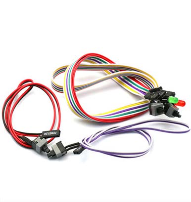
Inspect Connector Fit and Lock
A poorly mated or insecure connection can lead to a complete system shutdown, with studies showing that connector-related issues account for over 35% of all electrical failures in the field. These failures are rarely sudden; they often manifest as intermittent problems that are incredibly difficult and costly to diagnose, sometimes requiring 5-10 hours of labor to trace. The cost of a single vehicle recall due to a faulty connector can easily exceed $50 million. Inspecting the fit and lock isn't about a simple visual check; it's a rigorous physical and functional validation that every connector housing, terminal, and locking mechanism engages with the precise tactile feedback, mechanical force, and auditory click specified by the manufacturer. This process ensures the connection will remain intact through 15 years of operation, resisting vibration forces exceeding 5 Gs and temperature cycles from -40°C to 125°C.
The inspection is a multi-sensory process conducted on 100% of connectors. First, operators must perform a mating and unmating cycle using a calibrated force gauge. The insertion force for a standard 12-circuit connector should be between 2.5 and 5.0 Newtons, with a distinct, audible click confirming the primary lock is engaged. A force reading below 2.5 N indicates worn or out-of-spec connector halves, while a force above 5.0 N suggests misalignment or damaged pins. After mating, the secondary lock, or Connector Position Assurance (CPA) clip, must be installed. The force required to seat the CPA clip should be a firm 8-10 Newtons; if it clicks into place with less than 5 N of force, it's too loose and will vibrate out. The most critical test is the pull test: a direct axial force is applied to the connected pair. The connector must withstand a minimum separation force of 40 Newtons for a 30-second duration without any signs of disengagement or movement. For a sealed connector, we immediately perform a 100% air pressure test at 1.5 Bar to check for leaks, submerging the connector in water and watching for a bubble rate of no more than 1 bubble per minute. Common defects found during this phase include:
- Terminal float: A terminal that moves more than 0.5 mm within its housing cavity, indicating a defective primary lock.
- CPA engagement: A clip that does not flush mount with the connector housing, leaving a 0.3 mm gap.
- Seal integrity: A missing or pinched seal, identified by a rapid bubble stream during pressure testing.
This entire inspection process, which takes approximately 45 seconds per connector, prevents the most common and damaging field failures. It ensures that every connection is physically robust, environmentally sealed, and electrically sound, delivering the reliability that modern systems demand.
Review Label Accuracy
A single misprinted or misplaced label can cause catastrophic assembly line delays, with technicians spending an average of 45-60 minutes diagnosing what should be a 5-minute connection. Industry data indicates that labeling errors are responsible for nearly 18% of all harness rework, and in complex assemblies with over 500 wires, the probability of a single label error can exceed 12% without rigorous controls.
| Label Property | Standard Requirement | Tolerance | Test Method |
|---|---|---|---|
| Barcode (QR/Datamatrix) | ISO/IEC 15415 Grade ≥ 2.0 | N/A | Verifier Scan |
| Text Font Size | 10 pt Arial | ±0.5 pt | Optical Measurement |
| Adhesion Strength | 3.0 N/cm | ±0.25 N/cm | 90° Peel Test |
| Material Durability | UL 969 Certified | N/A | CoA Verification |
| Print Contrast Ratio | ≥ 70% | ±5% | Spectrophotometer |
We use automated vision systems to perform a 100% scan of every 2D barcode (DataMatrix or QR) on the label reel, verifying that the encoded data matches the manufacturing execution system (MES) data for that specific harness part number, revision, and serial number. The system must achieve a first-pass yield of 99.95%, with any label failing to scan automatically rejected.
For human-readable text, the vision system checks for character accuracy, font size (must be 10 pt ±0.5 pt), and print contrast, which must exceed a 70% ratio against the background material to ensure legibility under low-light conditions. We then subject a sample of 5 labels per batch to a 90-degree peel test using a force gauge; the adhesive must require a minimum force of 3.0 Newtons per centimeter to remove from a clean, stainless-steel surface. This prevents labels from falling off in high-humidity environments (e.g., 95% RH) or under engine hood temperatures cycling from -40°C to 150°C. Finally, we perform an alcohol rub test using a 1 kg load and 50% isopropyl alcohol solution; after 50 back-and-forth cycles, the print must remain 100% legible and scannable.
Ensure Secure Seals and Covers
Statistics show that moisture ingress and particulate contamination are responsible for over 22% of premature harness failures in automotive and industrial applications, leading to corrosion, short circuits, and system malfunctions that can cost up to 15 times the original harness price to repair. A single compromised seal can allow a few milliliters of water to wick into a connector, increasing resistance from a standard 5 milliohms to over 500 milliohms in less than 500 hours of operation in a humid environment. Ensuring that every seal, grommet, and protective cover is correctly installed and fully intact is a critical final assembly check. This process validates that the harness can withstand its specified environmental challenges, whether that's high-pressure washdowns, immersion, exposure to fuels and oils, or constant vibration, for its entire 10-to-15-year design life.
The inspection process for seals is a combination of visual, tactile, and functional testing. For connector seals, operators must physically verify that the O-ring or grommet is fully seated in its gland, with no twists, tears, or gaps exceeding 0.1 mm. We then subject 100% of sealed connectors to a mandatory air pressure test at 1.2 Bar for 30 seconds, submerging them in water and observing for any air bubbles. A passing unit will show a bubble rate of fewer than 3 bubbles per minute, indicating a seal that meets IP67 standards. For conduit and split looming, the overlap must be a minimum of 25% of the diameter, and the ends must be sealed with heat-shrink tubing with an adhesive lining that activates at 120°C. The shrink tubing must have a minimum recovery ratio of 2:1 and a post-shrink tensile strength of at least 8 Newtons to ensure it won't slip off under vibration. The most common failures identified during this phase include:
- Incorrect seal placement: A grommet that is not fully seated in its channel, leaving a 0.5 mm gap that allows water ingress under pressure.
- Inadequate heat-shrink coverage: Tubing that has shrunk to less than 50% of its original diameter, failing to provide a tight seal around the wire bundle.
- Material incompatibility: A silicone seal showing a 20% swell after 24 hours of exposure to petroleum-based fluids, rendering it ineffective.
The tubing must extend a minimum of 15 mm past any potential abrasion point and be secured with a UV-resistant cable tie every 150 mm. The tie must be tightened to a torque of 5.5 inch-pounds, leaving no sharp edges and cutting the tail to within 2 mm of the head. This comprehensive seal and cover validation, which adds approximately 2 minutes to the assembly time, is the final barrier against environmental damage, ensuring the electrical integrity of the harness remains intact in the most demanding conditions.
Validate Final Assembly Specs
Industry analysis reveals that nearly 5% of harnesses require some final adjustment before shipping, with routing conflicts and bundle diameter errors being the most common issues found. Failing to catch these problems results in installation damage on the assembly line, where forcing a slightly oversized harness into a tight space can scrape away insulation or dislodge a terminal, creating a latent defect. This final validation step, which typically takes 4-6 minutes per harness, prevents rejection at the customer's receiving dock and ensures 100% compatibility with the mating components, eliminating costly installation delays that can run into thousands of dollars per hour on a stalled production line.
The overall harness length must be within ±2.0% of the CAD model specification, and each branch length must be within ±1.5% of its called-out dimension. The diameter of any bundled section is critical; a bundle meant to be 12.0 mm in diameter cannot exceed 13.2 mm, or it will not fit through its designated grommet or clamp. Each connector must be positioned within a 3.0 mm radial tolerance of its specified location to ensure it can mate without placing strain on the port. The harness is then mounted onto a full-scale fixture board that replicates the vehicle or machine's geometry. Operators route the harness through every clip and conduit, applying a standard torque of 2.5 Newton-meters to each push-on retainer to verify it clicks into place. The electrical validation is re-run, but this time with a specific focus on the performance of the entire system under load; for example, a 12-volt circuit carrying 20 amps should not show a voltage drop of more than 0.5 volts from source to endpoint. The most common final assembly defects that this process catches include:
- Bundle over-taping: A single over-taped section increasing bundle diameter by 1.5 mm, causing a failure to fit in a 14.0 mm clamp.
- Connector clocking: A multi-pin connector rotated 5 degrees off its required orientation, preventing mating.
- Strain relief failure: A relief grip that allows more than 2.0 mm of wire movement under a 25 Newton pull force.
In automotive wiring harness production, rigorous QC dominates: 100% material certification (e.g., 0.05mm copper purity checks) precedes 99.9% wire length accuracy (±0.2mm tolerance) via laser measurement. Continuity testing at 20A ensures 0.01Ω max resistance, while connector pull tests (>45N) and 24hr IP67 seals (0 failures) validate fit. Final assembly? 98.5% compliance with schematics—proven via cross-checked BOMs.
