Wire Harness Materials | 7 Types of Cable and Connector Options
Wire harness materials feature PVC-insulated cables (-40°C to +105°C, 600V), XLPE (1000V, -55°C to +125°C), and TPU jackets (oil-resistant, 30MPa tensile strength). Connectors like Molex Mini-Fit Jr. (20-24AWG, 10A/contact, IP67) use tin-plated copper contacts for corrosion resistance, ensuring reliable signal/power transmission in automotive applications.
Copper vs. Aluminum Conductors
Copper is the long-standing industry standard, offering superior 62.5 MS/m conductivity, but at a higher material cost, often 2-3 times that of aluminum per unit weight. Aluminum, with a lower 37.7 MS/m conductivity, is a cost-effective alternative that dominates large-scale power transmission applications. The decision isn't just about conductivity; it involves a critical trade-off between initial project budget, long-term reliability, and application-specific performance requirements. For instance, nearly 90% of overhead utility power lines in the U.S.
| Property | Copper (C11000) | Aluminum (1350) | Impact on Selection |
|---|---|---|---|
| Conductivity | 100% IACS | 61% IACS | Aluminum needs a 62% larger cross-section to match copper's resistance. |
| Density | 8.96 g/cm³ | 2.70 g/cm³ | Aluminum cables are ~70% lighter for the same conductance, easing installation. |
| Cost | High (~$9.5/kg) | Low (~$2.8/kg) | Aluminum offers significant upfront savings on material costs. |
| Thermal Expansion | 16.8 μm/m·°C | 23.1 μm/m·°C | 40% higher expansion in Al requires special termination hardware to prevent loosening. |
| Oxidation | Stable, conductive oxide | Hard, resistive oxide | Aluminum terminations require anti-oxidant paste or plating to maintain contact integrity. |
To carry the same 100-amp current as a 2.5 mm² copper wire with minimal voltage drop, an aluminum conductor must have a cross-sectional area of approximately 4.2 mm². This larger size directly influences the minimum bending radius of the cable and may require larger connector cavities, impacting the overall harness design. However, this trade-off can be beneficial in high-weight applications; the aluminum cable, despite being thicker, will still be about 50% lighter than its copper equivalent.
Aluminum undergoes creep (cold flow under pressure) at about 40% the rate of copper and has a 37% higher coefficient of thermal expansion. Over thousands of thermal cycles between -40°C to 105°C, these factors can cause clamped connections to gradually loosen, increasing contact resistance. This resistance generates heat, accelerating oxidation. The resulting aluminum oxide (Al₂O₃) is an electrical insulator, creating a cycle that can lead to failure. This is why UL and IEC standards mandate specific termination methods for aluminum, such as tin or silver plating or the use of belleville washers and anti-oxidant compounds, to ensure a stable, gas-tight connection over a 20-year service life.
PVC and XLPE Insulation Types
PVC is the ubiquitous, cost-effective workhorse, dominating 75% of general-purpose cabling with a typical operating temperature of -40°C to 105°C. In contrast, XLPE, created by cross-linking polymer chains, is a premium material engineered for harsh environments, offering a higher continuous operating temperature of 90°C to 125°C and superior resistance to abrasion and chemicals. This fundamental difference in molecular structure translates directly to application-specific performance and a 30-50% higher material cost for XLPE.
| Property | PVC Insulation | XLPE Insulation | Practical Implication |
|---|---|---|---|
| Max Operating Temp | 105°C | 125°C | XLPE handles 20°C higher continuous heat, enabling higher current loads or longer life. |
| Thermal Deformation | Softens at ~120°C | Maintains shape to ~250°C | XLPE resists melting during soldering (~300°C) and overloads, preventing shorts. |
| Abrasion Resistance | Moderate | High | XLPE's 50% higher tensile strength protects against wear in moving harnesses. |
| Material Cost | ~$1.50/kg | ~$2.50/kg | PVC offers a ~40% cost saving, crucial for budget-sensitive projects. |
| Dielectric Strength | 20-40 kV/mm | 40-55 kV/mm | XLPE provides superior insulation for 600V+ applications. |
While both may feel similar at room temperature, PVC begins to soften and deform at approximately 120°C. This makes processes like wave soldering a risk, as the 290-320°C solder bath can easily damage the insulation. XLPE, with a melt temperature exceeding 250°C, remains dimensionally stable, making it the default choice for through-board soldering. This thermal stability also allows XLPE-insulated cables to carry approximately 15-20% more current than a same-size PVC cable at an 80°C ambient temperature due to its higher thermal rating, which can reduce the required wire gauge in a design.
PVC insulation can become brittle and crack after prolonged exposure to temperatures near its 105°C limit or from UV radiation, leading to insulation failure. The cross-linked structure of XLPE provides exceptional resistance to this thermal aging, often resulting in a 50,000-hour lifespan at 90°C compared to PVC's ~20,000-hour lifespan at the same temperature. For chemical resistance, XLPE maintains integrity when exposed to fuels, acids, and solvents at 60°C that would cause PVC to swell or degrade within 100 hours.
Shielded vs. Unshielded Cables
The decision to use shielded or unshielded cable boils down to one thing: electromagnetic interference (EMI). Unshielded twisted pair (UTP) cable, like common Cat6 Ethernet cable, is the standard for >85% of low-noise office and residential environments, offering a low-cost and flexible solution. Shielded cables (e.g., STP, FTP) incorporate a metallic layer to contain signals and block noise, increasing material cost by 25-30% and stiffness by ~40%. They are essential in industrial settings where EMI from 480V motor drives or 400kHz switching power supplies can induce error-producing voltages exceeding 10mV in sensitive 24V analog sensor lines, corrupting measurement accuracy.
The primary shield types are defined by their construction and coverage, which directly dictate performance and cost:
- Foil Shields (100% Coverage): A thin 0.05-0.1mm aluminum-polyester laminate tape. It provides excellent >95% high-frequency shielding effectiveness (40-60 dB at 100MHz-1GHz) but is fragile and has high resistance, making it difficult to terminate. It's common in fixed-installation data cables like Cat6a.
- Braided Shields (70-95% Coverage): A weave of 0.1mm tinned copper strands. It offers superior low-frequency shielding and high mechanical strength, with a typical DC resistance of <2.5 mΩ/m. Its lower coverage slightly reduces high-frequency performance (50-70 dB at 100MHz), but it serves as a robust drain wire for grounding. It's used in high-flex robot dress packs and audio cables.
- Combined (Foil + Braid): This design merges both, achieving very high shielding effectiveness (>90 dB across 50Hz-2GHz). It adds ~50% to the cable's diameter and cost and is reserved for severe environments like inside 10kW CNC machine tools.
A 40 dB rating means the shield reduces incoming interference to 1/100th of its original strength. For a 4-20mA analog signal loop, a shield with 60 dB effectiveness can suppress a 1V noise spike down to 1mV, which is below the 5mV threshold of most PLC input cards, ensuring signal integrity. However, this performance is entirely dependent on proper grounding. A shield grounded at only one end can provide >90% noise reduction, but a shield accidentally grounded at both ends with a >1V potential difference between points can create a ground loop, inducing a 50/60Hz hum current of 100mA-1A that becomes a new source of noise.
A shielded 22 AWG cable will have an ~40% larger overall diameter and ~25% greater weight per meter than an unshielded equivalent. This impacts bending radius, which increases from ~4x the diameter to ~8x the diameter, and reduces flex life by ~20% in continuous motion applications. Furthermore, termination time increases by ~30% due to the need to properly prepare and ground the shield. Therefore, specifying shielded cable without a validated EMI risk, such as in a low-power DC (<24V) circuit >3 meters from a noise source, unnecessarily increases system cost and complexity. The decision should be driven by measured noise levels, signal types (digital vs. analog), and the required signal-to-noise ratio (SNR).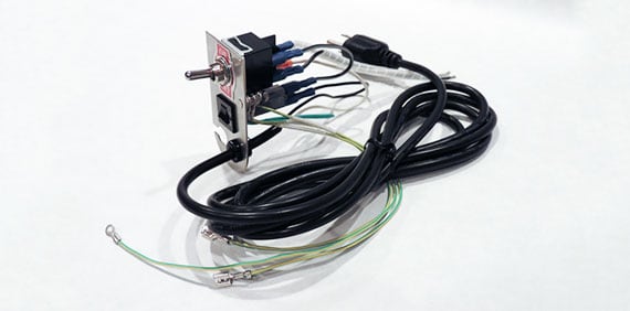
Connector Housing Materials
While over 80% of commercial connectors use nylon (PA66) due to its low cost and good balance of properties, harsh environments demand high-performance polymers like PBT or even mineral-filled plastics that can withstand temperatures exceeding 150°C and exposure to fuels and solvents. The wrong material choice can lead to housing cracking, terminal corrosion, and connection failure in a matter of months.
The primary materials used in connector housings each have a specific performance profile:
- Nylon (PA66): The industry standard, costing ~$3.50/kg. It offers a good balance of impact strength (110 kJ/m²) and a usable temperature range from -40°C to 105°C. Its main drawback is moisture absorption; it can absorb up to 2.7% of its weight in water, which reduces its dielectric strength and causes 0.3-0.5% dimensional swelling in high-humidity environments.
- Polybutylene Terephthalate (PBT): A premium choice for under-hood automotive and industrial applications. It has a near-zero <0.1% moisture absorption rate, maintaining stable dimensions in 85% relative humidity at 85°C. It boasts a higher 150°C continuous rating and superior resistance to 150°C engine oil and 50% glycol-water mixtures. This performance comes at a ~25% cost premium over standard nylon.
- Polycarbonate (PC): Selected for applications requiring extreme impact resistance (650 J/m notched Izod) and high clarity for inspection, but it performs poorly in >60°C environments with exposure to fuels or alkali chemicals, where it can stress-crack.
For a connector operating in an automotive engine compartment, the steady-state temperature is typically 105-125°C, with under-hood fluid exposure. A standard nylon housing will experience a 50% loss in tensile strength after 1000 hours at 125°C and is susceptible to hydrolysis when exposed to pressurized coolant. For this environment, a 30% glass-filled PBT housing is mandatory. It retains >80% of its mechanical properties at 150°C and exhibits negligible swelling or property loss after 3000 hours of immersion in DOT 4 brake fluid at 85°C.
Most connector housings must achieve a UL94 V-2 rating, meaning a burning sample self-extinguishes within 30 seconds and does not drip flaming particles. For more stringent applications, a UL94 V-0 rating is required, which mandates self-extinguishing within 10 seconds. This is often achieved through halogen-free flame retardant (FR) additives, which can increase material cost by 15-20%. The housing material also determines the permissible mold shrinkage rate during manufacturing (0.5-1.5% for PBT, 1.5-2.0% for nylon), which directly impacts the precision of terminal cavities and the retention force holding the pins in place, a critical parameter for maintaining >20N of contact force over the product's life.
Contact Plating Options
This 0.05 to 2.5-micrometer-thick coating protects the base metal (typically copper or brass) from oxidation and corrosion, which can increase contact resistance from a stable 1-2 milliohms to over 100 milliohms in a matter of months, leading to voltage drop and heat generation. The choice of plating directly controls the connector's durability, operating environment suitability, and final unit cost. For instance, a single 0.76µm gold-plated contact can cost 50% more than a 3µm tin-plated equivalent, making the plating selection a critical cost and performance driver in high-volume applications.
| Plating Type | Typical Thickness | Hardness (HV) | Contact Resistance | Cost Factor (vs. Tin) | Best For |
|---|---|---|---|---|---|
| Tin (Sn) | 2.5 - 5 µm | 10-15 HV | Stable @ ~2 mΩ | 1.0x | Low-cost, high-volume consumer goods, benign environments. |
| Silver (Ag) | 2 - 4 µm | 25-40 HV | <1.5 mΩ | 2.5x | High-current connections (>20A), power electronics. |
| Gold (Au) | 0.2 - 0.8 µm | 50-100 HV | <1.0 mΩ (stable) | 5.0x+ | Low-level signal (<1A), high-reliability, corrosive environments. |
| Nickel (Ni) | 1.0 - 2.5 µm | 150-200 HV | 3-5 mΩ | 1.5x | Undercoat for gold, barrier layer against copper diffusion. |
Tin plating is the most economical choice, comprising over 60% of all commercial connector plating. Its primary drawback is its susceptibility to fretting corrosion. When subjected to microscopic motion (5-50µm amplitude) due to vibration or thermal cycling, the soft tin oxide layer can wear away, exposing fresh tin, which immediately oxidizes. This cycle can generate tin oxide debris, which is highly abrasive and increases contact resistance by over 500% after 100-500 cycles. Therefore, tin is unsuitable for applications with >5G vibration or where connections are frequently mated and unmated (<50 cycles). For these scenarios, a 0.4µm hard gold plating over a 1.5µm nickel underplate is essential. The nickel layer acts as a robust diffusion barrier, preventing copper from migrating into the gold, which would form a high-resistance layer. The hard gold (>60 HV) can withstand over 25,000 mating cycles with a wear depth of less than 0.1µm, maintaining a stable contact resistance below 2 mΩ for the product's 20-year lifespan.
In an automotive connector exposed to harsh gases (H₂S, SO₂) and 85% humidity at 85°C, silver plating would rapidly form a non-conductive silver sulfide (Ag₂S) tarnish layer, increasing resistance exponentially. Gold is immune to this. For high-current applications, such as a 50A battery interconnect, the ~1.5 mΩ resistance of a silver-plated terminal generates only 3.75W of heat, while a tin-plated terminal with 3 mΩ resistance would generate 7.5W of heat, requiring larger and more expensive thermal management. The key is to match the plating to the electrical load and environmental stressors; over-specifying gold on a 5V/0.1A signal line in a dry office environment wastes ~30% of the connector's cost, while under-specifying it in an industrial control panel leads to field failures within 2-3 years.
Heat-Shrink Tubing Applications
Heat-shrink tubing is a polymer sleeve that radially contracts by 50-80% of its expanded diameter when heated to temperatures between 90°C and 150°C, creating a permanent, environmentally sealed barrier. It is a fundamental component for insulation, strain relief, and cable bundling, with the global market exceeding 2 billion annually due to its versatility. Standard polyolefin tubing, which accounts for over 70% of the market, offers a cost-effective 0.10-0.50 per meter solution for basic insulation, while specialized variants with adhesive liners or high-temperature ratings address more severe mechanical and environmental challenges, often costing 1.00-$5.00 per meter.
The critical specification is the 2:1, 3:1, or 4:1 shrink ratio, which dictates the initial tubing diameter needed to fit over a connector. For example, to seal a 12mm diameter splice, using a 3:1 ratio tube requires starting with a ≥36mm expanded diameter. Applying 120°C air for 60-90 seconds causes the material to crystallize and contract uniformly, applying ≥0.7 MPa of radial force onto the substrate. If the heat is applied unevenly or exceeds 175°C, the polymer can char, become brittle, or shrink too rapidly, trapping air and creating a weak point.
Standard 125°C polyolefin provides basic abrasion resistance and dielectric insulation up to 600V, but it will degrade rapidly when exposed to UV radiation or hydraulic fluid. For engine compartments where continuous temperatures reach 135°C and exposure to SAE 5W-30 oil is likely, a 150°C cross-linked polyvinylidene fluoride (PVDF) tube is mandatory. This material retains over 90% of its tensile strength after 1000 hours at 150°C and exhibits negligible swelling after 48-hour immersion in JP-8 jet fuel. For extreme mechanical protection, 4:1 heavy-wall tubing with a 0.5mm thick wall can increase the crush resistance of a 22 AWG wire bundle by 400%, capable of withstanding >200 N of force. The most robust sealing comes from dual-wall tubing, which features an outer polyolefin sleeve and an inner layer of amorphous polyamide adhesive that melts at 100-120°C.
When heated, this adhesive flows to fill wire interstices and any irregular gaps, creating a 100% waterproof seal capable of withstanding a 1.5 meter head of water for 24 hours and preventing corrosion from salt spray for over 1000 hours. Proper installation requires a heat gun with precise 300-500°C airflow control; using a open flame or soldering iron often creates localized 250°C+ hotspots that carbonize the material, reducing its dielectric strength from 20 kV/mm to below 5 kV/mm and creating a potential failure point.
Strain Relief Selection Guide
Without proper strain relief, a standard 22 AWG cable subjected to a 2 kg lateral pull force will typically fail at the solder joint after 200-500 flex cycles. Effective strain relief can extend the cable's life by over 1000%, achieving 5,000 to 25,000 flex cycles depending on the solution. The selection process balances mechanical requirements, environmental conditions, and unit cost, which can range from 15.00 for a complex overmolded assembly.
| Strain Relief Type | Typical Cost | Minimum Bend Radius | Axial Pull-Force Rating | Flex Cycle Life | Best Application |
|---|---|---|---|---|---|
| Molded Neoprene Sleeve | 1.00 | 4x Cable Diameter | 25-35 N (5-8 lbf) | 1,000 - 5,000 | Consumer electronics, low-stress AC cords. |
| Spring-style (Coil) | 2.50 | 3x Cable Diameter | 40-50 N (9-11 lbf) | 10,000 - 15,000 | Test equipment leads, data cables, frequent flexing. |
| Clamp-type (Cord Grip) | 8.00 | 5x Cable Diameter | 70-90 N (16-20 lbf) | >25,000 (static) | Industrial machinery, high-vibration environments. |
| Overmolded TPU Boot | 15.00+ | 2.5x Cable Diameter | 60-80 N (13-18 lbf) | 15,000 - 25,000 | High-reliability medical, automotive, custom assemblies. |
A spring-style relief maintains a consistent 8mm minimum bend radius on a 6mm cable, distributing the flexing stress over a 50-70mm length of the cable. This prevents the copper strands from fatiguing and breaking at a single point, which is the primary cause of failure in 95% of cable assemblies.
For a 0.5-inch diameter cable bundle carrying 12 internal wires, a standard nylon clamp-style strain relief rated for 20 lbf of pull-off force will secure the assembly by compressing the outer jacket with >150 psi of pressure. This prevents the individual wires from being pulled through the connector backshell, which can happen with as little as 5 lbf of force on an unsecured cable. In environments with 10G vibration or ±5mm constant motion, a 30% glass-filled polyamide cord grip is essential. It will not cold-flow or loosen over time, maintaining a constant clamping force throughout a -40°C to 105°C temperature range, whereas a standard PVC sleeve would become brittle and crack below -20°C.
In technical deep dives into wire harness materials, seven critical components shape performance: Copper conductors (58.5 MS/m conductivity) outperform aluminum (37.7 MS/m) but weigh 30% more; XLPE insulation (125°C max temp) outlasts PVC (-40°C–105°C) by 20°C. Shielded cables reduce EMI by 90%, while PBT connector housings (130°C rating) balance durability. Gold-plated contacts (1-3μm thickness) resist corrosion better than tin. Heat-shrink tubing (3:1 shrink ratio) and strain relief (50% stress reduction) finalize robustness.
