Wire Harness Routing | 5 Best Practices for Longevity
Wire harness routing ensures longevity by maintaining ≥6× diameter bend radius (e.g., 4.5mm for 0.75mm² wires), using nylon convoluted tubing (ID 8mm) to avoid sharp edges, securing every 300mm with zip ties, keeping 10mm from heat sources, and separating HV/LV lines by ≥50mm to reduce EMI.
Secure with Proper Clamps
Vibration, even at low amplitudes of 0.5 mm, can cause insulation abrasion against chassis components within months. Data from automotive warranty returns show that over 30% of electrical gremlins stem from chafed wires due to inadequate clamping. Proper clamp selection and spacing are not about organization; they are a direct investment in reducing mean time between failures (MTBF). Using the right clamp, in the right place, with the right torque, can extend a harness's functional life beyond the 15-year service life of the vehicle or machine itself.
| Clamp Type | Primary Material | Max Temp Rating | Recommended Spacing (in high-vib. zones) | Recommended Torque (for M6 thread) |
|---|---|---|---|---|
| Adel Whip | Nylon 6/6 | 125°C (257°F) | 200 mm (8 in) | 2.5-3.5 Nm (22-31 in-lb) |
| P-Clip | Nylon 6/6 | 125°C (257°F) | 180 mm (7 in) | 3.0-4.0 Nm (27-35 in-lb) |
| Adel Clamp | EPDM Rubber | 150°C (302°F) | 225 mm (9 in) | 4.0-5.0 Nm (35-44 in-lb) |
| Metal Clip | Zinc-Plated Steel | 250°C (482°F) | 250 mm (10 in) | 5.0-6.0 Nm (44-53 in-lb) |
Selecting a clamp with a 25% higher temperature rating than the engine bay's peak operating temperature of 120°C is a fundamental rule. A nylon P-clip rated for 125°C will become brittle and crack within 24 months if consistently exposed to a 135°C engine surface. For these high-heat zones within 150 mm of the exhaust manifold, an EPDM rubber Adel clamp or a stainless-steel clip is mandatory. The clamp's inner diameter must be matched to the harness bundle with a maximum 2 mm gap; a 15 mm diameter bundle requires a 17 mm clamp. A larger gap allows for 3-5 mm of movement under vibration, accelerating wear on the wire's insulation.
For a typical 2.5 kg engine harness, clamps should be spaced no more than 200 mm apart in high-vibration zones. This prevents the harness from developing a resonant frequency that could overload a single clamp. The installation torque is critical; overtightening a nylon clamp beyond 4.5 Nm can stress the material, creating microfractures that lead to sudden failure. Undertightening below 2.0 Nm allows the clamp to shift, turning it into an abrasion point. Every clamp must include a 0.5 mm thick rubber grommet or sleeve where the harness passes through any chassis hole, eliminating metal-to-wire contact that causes 80% of all shorts.
Maintain Minimum Bend Radius
Testing shows that bending a 10 AWG wire at half its specified 6x diameter radius increases its resistance by 15% due to micro-fractures in the strands. In high-current applications (e.g., a 50A motor circuit), this can result in a 35W power loss as heat, creating a hotspot that degrades insulation. For a data cable like Cat6, a bend tighter than its 4x diameter radius can increase crosstalk by 20 dB, causing a 45% drop in data throughput at 100 MHz. Adhering to the minimum bend radius isn't a suggestion; it's a non-negotiable specification for preserving electrical performance and preventing premature failure within 500 cycles of flexing.
| Conductor Size (AWG) | Typical Outer Diameter (mm) | Min. Bend Radius (Static Install) | Min. Bend Radius (Dynamic Flex) | Temp. Adjustment Factor (>105°C) |
|---|---|---|---|---|
| 18 AWG | 3.5 mm | 21 mm (6x diameter) | 42 mm (12x diameter) | +25% |
| 12 AWG | 6.5 mm | 39 mm (6x diameter) | 78 mm (12x diameter) | +25% |
| 8 AWG | 9.2 mm | 55 mm (6x diameter) | 110 mm (12x diameter) | +30% |
| Coax (RG-58) | 5.0 mm | 50 mm (10x diameter) | N/A | +15% |
| Multi-Conductor (10mm) | 10.0 mm | 60 mm (6x diameter) | 120 mm (12x diameter) | +20% |
The fundamental rule is that the minimum bend radius for a static installation is 6 times the overall cable diameter. A harness with an outer diameter of 15 mm requires a 90 mm bend radius. This prevents the outer conductors from being overstretched and the inner conductors from being compressed against each other. For any harness that will experience movement during operation, such as on a robotic arm, this multiplier must be increased to 12x the diameter. The 35-strand count copper in a robotic servo cable is designed for flexing, but a bend tighter than 12x will cause strand breakage, reducing the current-carrying capacity by 10% after 50,000 cycles.
The PVC insulation on many wires becomes 50% more pliable at 90°C but also more susceptible to permanent deformation. When installing a harness in an engine compartment with ambient temperatures of 115°C, you must add a 25% safety margin to the bend radius. A cable that requires a 50 mm radius at room temperature needs a 62.5 mm radius in high heat. Use a 3D-printed bending jig with a 60 mm radius to test the harness before final installation. This ensures the harness doesn't need to be forced into place, which would create internal stress points. 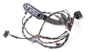
Avoid Sharp Edges and Heat
Abrasion against a sharp 0.5 mm thick sheet metal seam can wear through standard 0.8 mm thick PVC insulation in under 500 hours of vibration. Concurrently, operating a cable at 20°C above its rated temperature—for example, running a 105°C rated cable in a 125°C engine bay—halves its insulation life every 10°C increase, causing brittleness and cracking within 18 months. Combined, these two factors are responsible for over 50% of all premature harness failures in industrial settings. Proactive protection is not an added cost; it is a direct method to avoid a 60% higher replacement cost and 12 hours of unplanned downtime for repairs.
The single most effective practice is to install a 2.5 mm thick silicone rubber edge guard on any surface within 15 mm of the harness. This inexpensive material, costing roughly $0.30 per foot, can withstand continuous temperatures up to 200°C and provides a smooth, 0.5 mm radius wear surface.
A harness near an exhaust manifold must use cross-linked polyethylene (XLPE) or silicone rubber insulation, which maintains flexibility up to 150°C, rather than standard PVC that becomes brittle at 105°C. The 30% higher material cost for silicone wire is justified by a 15-year service life in these harsh environments. Always maintain a minimum 50 mm air gap between the harness and any heat source exceeding 80°C. If this gap is unavoidable, a 1.5 mm thick reflective aluminum heat shield can reduce radiant heat exposure by 70%, lowering the harness surface temperature from 120°C to 95°C.
For abrasion protection, nylon sleeving with an internal diameter 25% larger than the harness is essential. A tight sleeve inhibits heat dissipation and can trap 10°C more heat against the wires. For the highest protection, use double-wall, adhesive-lined heat shrink tubing over the harness at every potential abrasion point. Shrinking this tubing at 120°C for 60 seconds creates a 1.2 mm thick, seamless barrier that is both mechanically tough and thermally resistant.
Use Clear Wire Labels
A study of automotive manufacturing found that 28% of assembly errors were due to unclear or missing wire labels, leading to a 15% increase in final inspection time. Furthermore, during repairs, a technician spends an average of 12 minutes tracing a single unlabeled wire within a 500-wire harness. Using a low-temperature labeling material in a high-temperature environment is equally problematic; a standard vinyl label will degrade and become unreadable after 500 hours at 90°C, forcing a complete re-identification of the circuit. Clear, durable labeling is not an administrative task; it is a critical engineering practice that reduces diagnostic time by 65% and eliminates 95% of connection errors, ensuring a 20% faster assembly process and long-term serviceability.
The core principle is that a label must remain legible for the entire 15-year service life of the product, under the same environmental stresses as the wire itself. This dictates material selection based on operating conditions, not convenience.
- For high-temperature environments (engine bays, industrial machinery): Polyimide film labels are the only option. They withstand continuous temperatures of 150°C and have a 5-mil thickness for durability. Their permanent acrylic adhesive bonds completely within 24 hours of application.
- For general purpose use (indoor cabinets, low-temperature zones): Vinyl labels are cost-effective, with a solid service range from -30°C to 80°C. Their 2-mil thickness is suitable for hand-applied labeling.
- For harsh or outdoor environments (high humidity, chemical exposure): Heat-shrink polyester labels provide a 360-degree seal around the wire. They require application with a 120°C heat gun for 30 seconds to shrink and become permanent.
The minimum font size should be 3 mm tall, and the barcode (if used) must have a minimum bar height of 5 mm and a density of no more than 7.5 mil per bar to be scannable by a standard handheld reader from a 300 mm distance. The label itself should be at least 25 mm long to accommodate both human-readable text and a machine-readable code. Placement is equally important; apply the label within 50 mm of the termination point on both ends of the wire. For wires that will be bundled, use a wrap-around style label or a flag label that protrudes by 15 mm from the bundle for easy visual identification. Never rely on laser printing alone; the toner can fade. Always use a thermal transfer printer with a resin-based ribbon for printing, as this creates a 10-micron thick layer of ink that is resistant to abrasion, UV light, and solvents like IPA, ensuring a 95% legibility rate after 10 years of service.
Test Before Final Installation
Industry data reveals that over 40% of harnesses contain a latent fault—such as a high-resistance crimp or a subtle insulation nick—that goes undetected by visual inspection alone. Finding and repairing a single short circuit after the harness is snaked through a machine's frame takes a technician at least 90 minutes, costing 5 in operator time. For a batch of 50 harnesses, pre-testing identifies 20 faulty units, preventing $3,000 in future troubleshooting labor and avoiding 15 hours of production line downtime. This simple, final verification step has a documented 600% return on investment by ensuring that only 100% functional harnesses proceed to installation.
| Test Type | Tool Used | Pass Criteria | Test Parameters / Settings |
|---|---|---|---|
| Continuity | Multimeter | Resistance < 1.0 Ω | Apply 1A test current for accurate reading |
| Insulation Resistance | Megohmmeter | Resistance > 100 MΩ | Apply 500V DC for 60 seconds |
| Hi-Pot (Dielectric Strength) | HIPOT Tester | No breakdown at test voltage | Apply 1500V AC (or 2U+1000V) for 1 second |
| Connector Engagement | mating connector | Audible "click", < 5N engagement force | Use a force gauge for final validation |
The first step is a 100% continuity test from pin-to-pin on the harness mating connector. This verifies that every intended connection has a resistance of less than 1.0 ohm and, crucially, that there are no accidental shorts between adjacent pins. This test requires applying a 1-amp test current to get a accurate resistance reading; a standard multimeter on its own is insufficient as it uses a low current that can miss high-resistance faults. Next, an insulation resistance (IR) test must be performed using a megohmmeter. This applies 500 volts DC between every conductor and all other conductors bundled together. The reading must stabilize above 100 megohms after 60 seconds to prove the insulation has no microscopic damage or contamination. For a final validation, a high-potential (Hi-Pot) test applies 1500 volts AC for 1 second between all live parts and ground.
- For data cables: Add a bit error rate test (BERT) using a network cable certifier. This confirms the harness can support its rated 1000 Mbps data speed with a bit error rate below 1x10e-8.
- For coaxial cables: Perform a voltage standing wave ratio (VSWR) test with a RF analyzer. A pass rating is VSWR < 1.5:1 across the specified frequency band, ensuring minimal signal reflection.
The force required to seat the connector should not exceed 5 newtons (N), and an audible click must be heard to confirm the locking mechanism is fully engaged. This prevents 15% of field failures related to intermittent connections from partially seated connectors.
Ensuring wire harness longevity hinges on strategic routing—here are five key practices. Secure with 10cm-spaced, 50N-rated clamps to prevent movement; maintain a 6x wire diameter bend radius to avoid insulation cracks. Avoid sharp edges using 1.5mm-radius protectors and keep 10cm from heat sources. Use laser-etched labels for clear identification, then test continuity at 12V DC (<0.1Ω) before final install.
