Ignition Coil Wire Harnesses: Selection, Materials, Manufacturing & Custom Solutions
Introduction
We are a Professional Custom Ignition Coil Wire Harness Assembly Manufacturer in China. An ignition coil harness — often referred to as a coil-on-plug (COP) harness or ignition coil wire loom — is the dedicated wiring assembly that bridges a vehicle's engine control unit (ECU/PCM) and the individual ignition coils mounted directly atop each spark plug. Unlike a generic engine-bay wire bundle, the ignition coil harness carries both continuous 12 V/24 V primary power and precision-timed switching signals that fire each coil at millisecond-accurate intervals.
Physically, the assembly consists of multiple pigtail leads — one per cylinder — that break out from a central main connector (or distributed PCB header) and terminate in sealed, polarized coil connectors. Between the terminations, the conductors are bundled, laced, and sleeved to survive a uniquely hostile envelope: ambient temperatures that cycle from −40 °C to +125~150 °C near exhaust components, constant vibration, splashing engine oil, fuel vapor, coolant mist, and road salt spray.
Because the ignition event generates significant inductive voltage spikes (the coil itself steps 12 V up to 20,000–40,000 V at the secondary side), the harness must provide clean signal isolation, robust dielectric insulation, and mechanically secure terminations. A single loose crimp or chafed wire in this harness doesn't just cause a misfire — it can back-feed voltage spikes into the ECU driver stage and destroy expensive electronics. That is why material specification, routing protection, and 100 % electrical verification are non-negotiable in any professional ignition coil harness build.
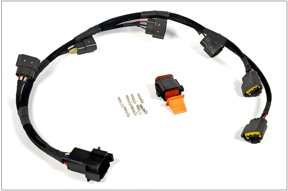
Classification & Types of Ignition Coil Harnesses
Ignition coil harnesses are not one-size-fits-all. They are classified along three practical axes, each of which drives different design rules and bill-of-materials choices:
By Vehicle / Duty Class
|
Class
|
Typical Environment
|
Harness Implication
|
|---|---|---|
|
Passenger Car (OEM & Aftermarket)
|
Moderately packaged engine bay, −30 °C … +105 °C
|
Compact routing, thin-wall wire (FLRY / TXL), molded clip mounts
|
|
Heavy-Duty / Commercial Truck & Diesel
|
High sustained under-hood heat (+120 °C+), vibration, oil soak
|
Thicker insulation (GXL / SXL), dual-wall heat shrink, reinforced conduit
|
|
Motorcycle & Powersports
|
Extremely tight routing, high vibration, and wash-down exposure
|
Minimalist breakouts, high-flex stranded tinned copper, adhesive-lined sealed connectors
|
|
Marine / Industrial Engine
|
Salt spray, high humidity, fuel vapor
|
Corrosion-resistant plating (tin or gold), IP67+ seals, anti-wicking wire construction
|
By Electrical Configuration
-
Coil-on-Plug (COP) Sequential Harness — One discrete connector per cylinder (most modern 4-, 6-, and 8-cylinder engines). Signal wires are individually addressed by the ECU. Requires precise pin-to-pin mapping.
-
Shared-Power / Distributed Harness — Common 12 V and ground bus shared across all coils, with only the trigger signal individually wired. Economical, but places a higher current on the shared feed conductor.
-
Wasted-Spark / Older Distributor-Less Configurations — Two plugs fired simultaneously per coil; wiring logic differs, and coil pack location may be remote rather than plug-top.
By Performance / Specification Tier
-
Standard OEM-Replacement Tier — Meets stock temperature and durability specs; emphasis on correct fit, correct connector keying, and long-term reliability at reasonable cost.
-
High-Performance / Motorsport Tier — Upgraded conductors (silicone or PTFE-jacketed where needed), lightweight thin-wall insulation, race-grade sealed connectors, and sometimes braided shielding to suppress EMI in data-rich vehicles with sensitive telemetry.
Quick Selection Rule: If the harness routes within 150 mm of an exhaust manifold or turbocharger hot side, specify cross-linked XLPE insulation (GXL/TXL) and polyamide (Nylon) conduit, not standard PVC. PVC softens past ~80 °C and will eventually slump, exposing conductors.
Purpose & Core Functions
The ignition coil harness performs four tightly coupled functions that go far beyond "just carrying electricity":
-
Precision Signal Delivery — The ECU's coil driver transistors switch each coil primary circuit on/off with microsecond timing. The harness must preserve signal integrity so that dwell time (how long the coil charges) and spark advance are not distorted by excessive IR drop or crosstalk.
-
Stable Power Feed — Each coil can draw 5–10 A during saturation on a 12 V system (more on 24 V diesels with smart current-limiting controllers). The supply conductors must be adequately gauged (typically 18–14 AWG depending on cylinder count and lead length) to prevent voltage sag that retards spark energy.
-
Voltage-Spike Isolation — Every time the coil collapses its magnetic field, a high-energy transient propagates on the primary side. Proper harness layout (adequate conductor spacing, good ground reference, and intact insulation) prevents these transients from jumping to adjacent sensor signal wires — a common root cause of erratic MAP/MAF / crank-sensor behavior.
-
Environmental Survival — Oil, thermal cycling, and vibration are the real enemies. The harness is located within the engine's most aggressive zone. Its protective sleeving, seal placement, and strain-relief design determine whether it lasts 5,000 miles or 150,000 miles.
In short, the ignition coil harness is a controlled-impedance, environmentally armored power/signal distribution network, and every material choice either adds margin or removes it.
Material Selection — The Engineering Detail
This is where an ignition coil harness lives or dies. Below is the material specification framework we apply to every custom build.
Connector Selection (Housings, Terminals & Seals)
Engine-bay connectors must resist heat, vibration, loosening, moisture ingress, and contact corrosion.
|
Requirement
|
Recommended Solution
|
Notes
|
|---|---|---|
|
Temp rating 125–150 °C region
|
TE Connectivity AMP Junior Power Timer (JPT) series — PA66 / PBT housings, −40…+130 °C rating; MCON 1.2 / 1.5 / 2.8 mm systems for sealed variants
|
JPT is the global de facto coil-connector platform; polarized housings prevent mis-mating
|
|
Waterproof / underbody splash zone
|
Aptiv (Delphi) Weather Pack or Metri-Pack — silicone rubber seals, IP67 capable
|
Friction-lock with secondary lock (TPA optional); excellent for marine/truck
|
|
High-vibration security
|
Housings with CPA (Connector Position Assurance) latches or integral locking lance + strain-relief boot at exit
|
CPA prevents "walking open" from thermal expansion cycles
|
|
Terminal plating
|
Tin-plated brass for cost-effective general use; gold flash for low-signal, high-corrosion environments
|
Tin is the workhorse; gold is specified only where salt-spray / coastal exposure justifies it
|
|
Wire-range fit
|
Open-barrel F-crimp terminals sized for 0.5–2.5 mm² (20–16 AWG), typical coil wiring
|
Crimp must bite conductor strands (not just insulation) to achieve a gas-tight joint
|
Pro tip for coil pigtails: Always verify the mating tab width (2.8 mm vs. 6.3 mm) and pin count (2-pin vs. 3-pin with tach/RPM sense) against the actual coil pack. Aftermarket "universal" connectors that get the keying wrong cause harness scrap before the vehicle ever starts.
Wire Conductor & Insulation Selection
The conductor is almost always stranded soft-annealed copper (ASTM B3/B8), typically tinned for solderability and corrosion resistance in damp locations. Plain bare copper is acceptable in sealed interior runs; tinned is preferred everywhere else in the engine bay.
For insulation, cross-linked polyethylene (XLPE) is the engineering minimum for coil harnesses:
|
Wire Standard / Type
|
Insulation
|
Wall Profile
|
Max Continuous Temp
|
When to Specify
|
|---|---|---|---|---|
|
GPT (SAE J1128)
|
PVC
|
Std
|
80 °C (176 °F)
|
⚠️ NOT for engine bay. Cabin-only, low-heat accessories only
|
|
GXL (SAE J1128)
|
XLPE
|
Thin wall
|
125 °C (257 °F)
|
✅ Default choice for most coil harnesses — balanced abrasion & flexibility
|
|
TXL (SAE J1128)
|
XLPE
|
Extra-thin
|
125 °C
|
✅ Tight-bundle, weight-sensitive builds; must be sleeved (loom/braid) since thin wall = less abrasion buffer
|
|
SXL (SAE J1128)
|
XLPE
|
Thick wall
|
125 °C
|
Exposed single-runs near sharp edges / heavy truck chassis; stiffer bend radius
|
|
FLRY-B (DIN/ISO / European)
|
Thin-wall PVC-XL blend
|
Very thin
|
105–125 °C
|
European OEM replacement; metric sizes (0.5 / 0.75 / 1.0 mm²)
|
|
AVSS (JASO / Japanese)
|
Thin-wall PVC
|
Ultra-thin
|
80–100 °C (some grades 120 °C)
|
Japanese platforms where space is extreme; confirm temp class before specifying
|
Typical coil-harness gauge range:
|
Function
|
Recommended AWG / mm²
|
Rationale
|
|---|---|---|
|
Signal / switched trigger line
|
20–22 AWG (0.35–0.5 mm²)
|
Low current, logic-level switching; must handle ECU driver sink current
|
|
12 V power feed (shared bus)
|
16–14 AWG (1.0–2.0 mm²)
|
Must carry cumulative coil current without >0.5 V drop over harness length
|
|
Ground return (individual or common)
|
Matched to power feed or one size larger
|
Undersized ground is the #1 cause of intermittent coil misfires
|
All wires specified for ignition coil duty should carry UL recognition or SAE/DIN compliance markings, inkjet-printed on the insulation jacket for traceability.
Auxiliary & Protective Materials (Sleeving, Taping, Sealing)
Even perfect wire and connectors fail if the outer protection system is wrong. The coil harness lives where a dangling unprotected lead will rub through in < 20 operating hours.
|
Auxiliary Material
|
Material Grade
|
Where & Why
|
|---|---|---|
|
Split Corrugated Conduit (Loom)
|
PP (polypropylene) for ≤105 °C zones; PA6 / PA12 Nylon for ≥120 °C radiant heat zones
|
Main backbone sleeve. Nylon conduit survives direct proximity to exhaust components; PP is fine for cooler routing paths
|
|
Adhesive-Lined Dual-Wall Heat Shrink (DW-AD)
|
Polyolefin + inner thermoplastic adhesive, 125–135 °C rating
|
Applied over each crimp-to-connector transition. The adhesive melts and bonds to insulation + terminal barrel, creating a moisture block that prevents oil-wick and corrosion creep
|
|
Fleece / Cloth Harness Tape
|
Acrylic-coated PET fleece
|
Wrapped at breakouts and overlapped bends. Fleece tape resists unraveling under heat, absorbs vibration (rattle suppression), and won't leave hard plastic edges that abrade neighboring hoses
|
|
PVC / Vinyl Electrical Tape (Premium Grade)
|
Flame-retardant, UV-stable
|
Secondary overwrap at conduit terminations; never the primary insulation in an engine bay
|
|
Cable Ties (Zip Ties)
|
PA66 Heat-Stabilized Nylon, 125–150 °C rating
|
Mounting ties spaced per drawing (typically 150–250 mm pitch on backbone). Stainless-steel ties for extreme vibration/underbody if required
|
|
Grommets / Backshells / Strain-Relief Boots
|
Neoprene or silicone rubber
|
At firewall pass-throughs and connector exit points — prevents fatigue fracture of conductors at the stress concentration
|
Processing & Manufacturing — How a Professional Coil Harness Is Built
Universal Wire Harness Processing Steps (The Build Sequence)
Every ignition coil harness — whether a 4-cylinder COP pigtail set or an 8-cylinder fully loomed assembly — follows the same disciplined sequence dictated by IPC/WHMA-A-620 workmanship standards:
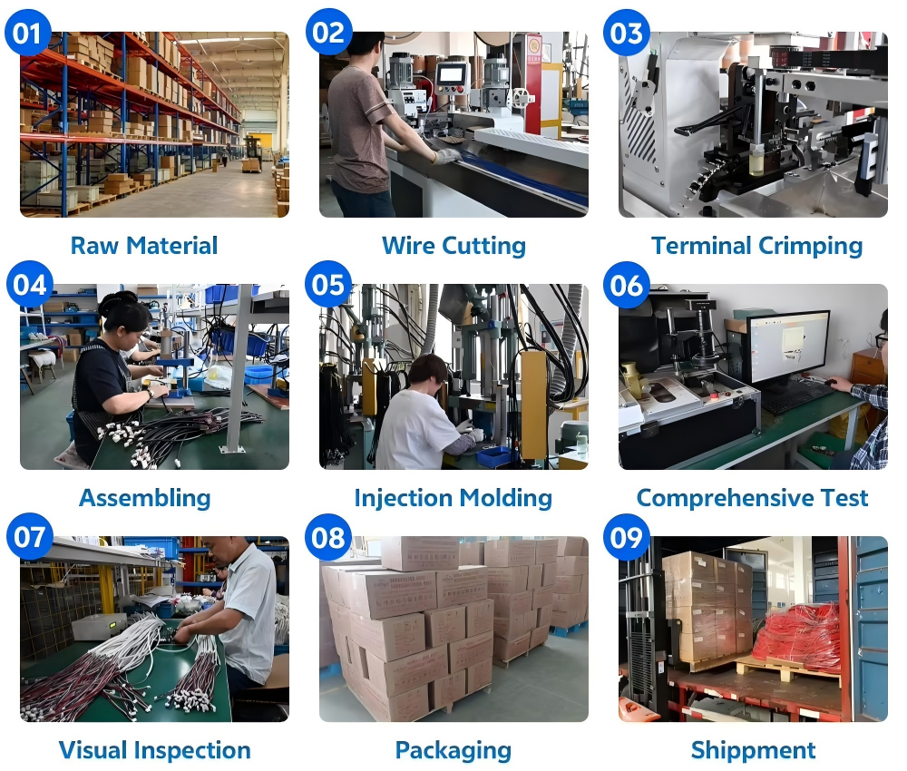
Dimensional Control & 100 % Continuity Test Guarantee
Length and branch-breakout control is what makes a coil harness install cleanly — too short and the conduit tears at the connector; too long and the harness drapes against hot exhaust or moving throttle linkage.
-
How we control it: Every harness is assembled against a 1:1 scale formboard engraved/pinned to the drawing's coordinate scheme. Each branch length, breakout datum, and conduit trim point is a physical dimension on that board. During assembly, operators route the loomed bundle on the board and verify that each branch reaches its labeled anchor point with the designed service loop (extra slack — typically 10–20 mm — to avoid tension at mounts). For production runs, a first-article inspection (FAI) unit is fully measured (branch lengths, connector-to-connector distances, breakout offsets) and signed off before the line runs.
-
Inline checks: Conduit cut lengths are verified with a steel rule before taping; tie-wrap positions are checked against board pegs. Any deviation beyond the tolerance band triggers a line stop and tooling review.
Then comes the gatekeeper — 100 % Electrical Testing:
Every single ignition coil harness — not a sample, not a batch average — receives a full automated continuity and isolation (Hi-Pot where specified) test before packing.
The harness is mated to a dedicated test fixture (pogo-pin interface or duplicate connector set) linked to a programmable tester. The test cycle — typically under 30 seconds per piece — performs:
|
Test
|
Condition
|
Pass Criterion
|
|---|---|---|
|
Continuity (Open-Circuit Check)
|
Low-current source (~100 mA) injected end-to-end on every pin-to-pin path
|
Resistance < 50 mΩ (typical); any open → reject
|
|
Mis-Wire Check (Crossed-Pin Check)
|
Matrix scan confirms only the intended pairings exist
|
Zero tolerance — one crossed pin kills an ECU channel; auto-fail
|
|
Short / Isolation Check
|
Resistance measured between mutually isolated conductors (and between each conductor and shield/drain if present)
|
> 1 MΩ (often > 10 MΩ spec); any short → reject
|
|
Hi-Pot / Dielectric Withstand (optional, upon request/voltage class)
|
500–1500 VAC / DC applied between conductors and to the shield/ground plane for a dwell time
|
Leakage current below threshold (typically < 5 mA); no breakdown/arc
|
Custom Ignition Coil Wire Harness Case
Ignition Coil Harness
Ignition Coil Connector
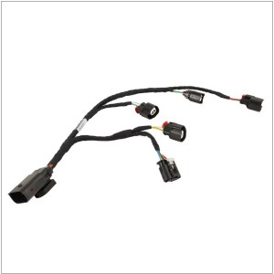
Fuel Injector Wiring Harness
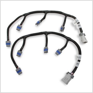
EFI LS Coil Ignition Harness
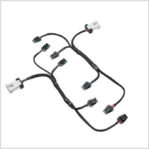
Coil Pack Harness
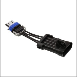
Coil Adapter Harness
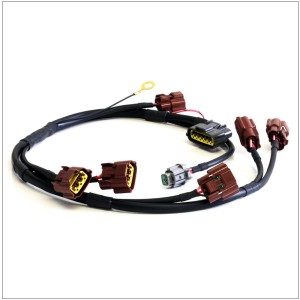
S1 Coil Harness
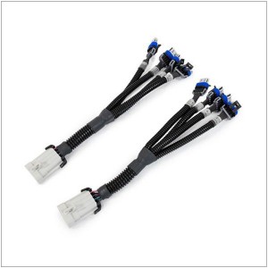
LS Ignition Coil Relocation Harness
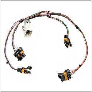
Ignition Coil Wiring Harness
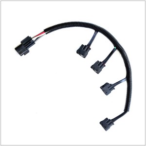
Ignition Coil Wire Harness
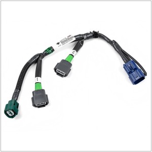
Ignition Coil Sub Harness
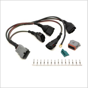
Ignition Coil Harnesses
We Support Custom Wire Harness Assembly
- Connectors: Support TE, Deutsch, Aptiv, Amphenol, Sumitomo, Yazaki, etc.
- Wire Gauge:
- depends on your needs
- recommended by us
- Wire Colors: Available in a wide range, including white, black, red, yellow, blue, green, brown, orange, purple, grey, and more.
- Wire Length: Fully customizable to your specifications.
- Wiring Diagram: Tailor-made to meet your project needs.
- Custom type:
- Send drawing to customize.
- Send a sample to customize.
- Tell us as many details as possible to customize.
- Minimum Order: 100 pieces.
Why Engineers Specify Us
-
Materials traceability — Using UL-recognized / SAE/DIN-compliant wire and name-brand connectors (TE, Deutsch, Aptiv, Molex, Sumitomo, Yazaki, Lear, Amphenol, etc.) from qualified supply chains.
-
No "visual-only" quality — Crimp height data, pull-test records, and 100 % electrical test tickets are standard, not upsells.
-
Dimensional discipline — Formboard-controlled assembly means your harness drops in the same way, unit after unit.
-
Scalable — From prototype 5-piece runs to 10,000+ scheduled releases with blanket orders.
Ready to eliminate ignition misfires caused by tired, oil-soaked wiring?Send us your schematic / coil connector photo / sample harness — or even just the engine type and cylinder count — and we'll respond with a DFM review and formal quote within 48 hours.Preferred formats: PDF drawing, Excel BOM/pinout table, or the old harness itself in a bubble mailer — we'll reverse-engineer it accurately and propose upgrades where the original was under-specified.
All technical recommendations above (wire temperature class, connector series, test methodology) align with industry-recognized references, including SAE J1128, IPC/WHMA-A-620, and OEM connector ecosystems from TE Connectivity, Aptiv, and Molex. The final specification should always be validated against your specific engine platform's service documentation and operating envelope.
Customize Your Wire Harness
Send your sample or drawing/schematic for quote price→ Feedback with quotation(1~3 days) → Confirm quotation → Arrange sample you for approval→ [Make mold if needed (7 days) →Mold test] → Making samples(1~3 days)→ Samples test(Approval) → place order for Mass production(2~3 weeks)→ Quality checking→ Packing → Delivery → After Service → Repeat Order.
